The post We’re going to LogiMAT 2026! appeared first on ADVANCED Motion Controls.
]]>
For the first time, ADVANCED Motion Controls is exhibiting at LogiMAT, Europe's biggest annual logistics exposition.
LogiMAT 2026 will feature 10 exhibit halls filled with companies from around the globe that make up the intralogistics and process management industries.
You can find the ADVANCED Motion Controls team in Hall 8 at stand 8A10.
When?
March 24-26
Tuesday-Thursday
9:00 AM – 5:00 PM
Where?
Messe Stuttgart
Messepiazza 1
70629 Stuttgart
Germany
Hall 8, Stand 8A10
The post We’re going to LogiMAT 2026! appeared first on ADVANCED Motion Controls.
]]>The post Stevens Institute of Technology – Robot-Assisted Stroke Rehabilitation appeared first on ADVANCED Motion Controls.
]]>The Challenge: Beyond "Myopic" Robotics
Stroke remains a leading cause of long-term disability, with over 800,000 cases annually in the U.S. alone. While robot-assisted rehabilitation offers a scalable solution to the shortage of physical therapists, a critical requirement for neuroplasticity is "active effort." If a robot does all the work, the patient remains passive, and no motor learning occurs.
Professor Damiano Zanotto and his team at Stevens Institute of Technology sought to solve this by developing a "smart" robotic system using Reinforcement Learning (RL). They hypothesized that a controller could "learn" the patient's needs in real-time—offering support only when necessary (Assist-as-Needed) and forcing effort when possible.

The Hurdles: The Gap Between Theory and Hardware
Moving from a theoretical control algorithm to a physical machine presents two distinct hurdles: technical and financial.
- Technical Latency: Traditional "myopic" controllers are reactive, adjusting only after an error occurs. The Stevens Institute team needed a system capable of "Curriculum Learning"—processing neural network outputs and adjusting motor torque instantly (at 1 kHz) to keep the patient in the optimal learning zone.
- The Academic Constraint: Validating a new theory requires high-performance, industrial-grade components. However, academic budgets are frequently strained. Researchers often face a difficult trade-off: compromise on hardware performance to save costs, potentially invalidating their results, or stall the project due to lack of funding.
The Solution: A Partnership for Innovation
To bridge the gap between theory and practicality, the team utilized the ADVANCED Motion Controls University Outreach Program.
Professor Zanotto and Stevens Institute of Technology had previously worked with AMC's University Outreach Program for a haptic joystick project several years before. So when this project needed a servo drive, Professor Zanotto knew exactly who to call.
Recognizing the project's potential contribution to the medical community, AMC donated DZEANTU-020B200 digital servo drives to the lab. This partnership provided the team with industrial-grade hardware without the prohibitive costs, allowing them to focus on the engineering challenge rather than procurement limitations.

The Hardware Advantage:
The DZEANTU drives were integrated into a custom Cable-Driven Parallel Robot (CDPR).

- High-Speed Communication: The drives communicated with the real-time target machine via EtherCAT, achieving the critical 1 kHz update rate required by the RL algorithms.
- Precision Control: The digital drives provided the precise current loop control necessary to render smooth, haptic forces, making the robot feel like a natural extension of the therapist.
The Results: Validated Success
With the financial burden eased and the technical requirements met, the team successfully validated their Reinforcement Learning Assist-as-Needed (RL-AAN) controller. The study showed that users trained with the AMC-powered system demonstrated:
- Reduced Robot Dependence: Users were forced to contribute significantly more active effort than with traditional controllers.
- Superior Retention: Users retained better trajectory accuracy even after robotic assistance was removed.
By getting high-performance servo drives into the hands of these researchers, ADVANCED Motion Controls became an integral part of a project that pushes the boundaries of stroke recovery.
About the University Outreach Program
Since 2004, ADVANCED Motion Controls has partnered with students, researchers, and professors to further the educational process in motion control. Our objective is to ease the financial burdens of establishing practicality while proving theory.
Whether you are working on a master’s thesis, a classroom project, or a laboratory upgrade, we are proud to become a pending part of your team. We offer:
- Donated or Discounted Equipment: From new servo drives to perfectly functional discontinued units from our "free drives list."
- Technical Support: Direct access to our engineering team to help you select the best product for your specific application.
- Real-World Experience: Putting industrial-grade equipment into the hands of future engineers.
Have a project? Tell us about your mission.
Contributions are typically limited to U.S. institutions or international projects involving U.S. institutions.
The post Stevens Institute of Technology – Robot-Assisted Stroke Rehabilitation appeared first on ADVANCED Motion Controls.
]]>The post What is Closed-Loop Control: The Foundation of Modern Automation appeared first on ADVANCED Motion Controls.
]]>At its core, closed-loop control is a simple idea: measure what happened, compare it to what you wanted, and automatically correct the input to hold a desired setpoint.
That feedback step is what turns a “set it and hope” process into something that can hold a target even when real life gets in the way—changing loads, temperature drift, friction, wear, voltage sag, or airflow shifts.
If you’ve ever watched a thermostat “hunt” around a temperature, or a servo axis land precisely on a commanded coordinate, you’ve seen closed-loop control doing what it does best: correcting reality until it matches the target.
In this article, we’ll break closed-loop control down into plain terms: what it is, how it works, and how it compares to open-loop control. Then we’ll zoom in on the practical side—performance traits, tuning, and how closed-loop feedback is actually implemented in industrial systems like servo drives.
What is a closed-loop control system?
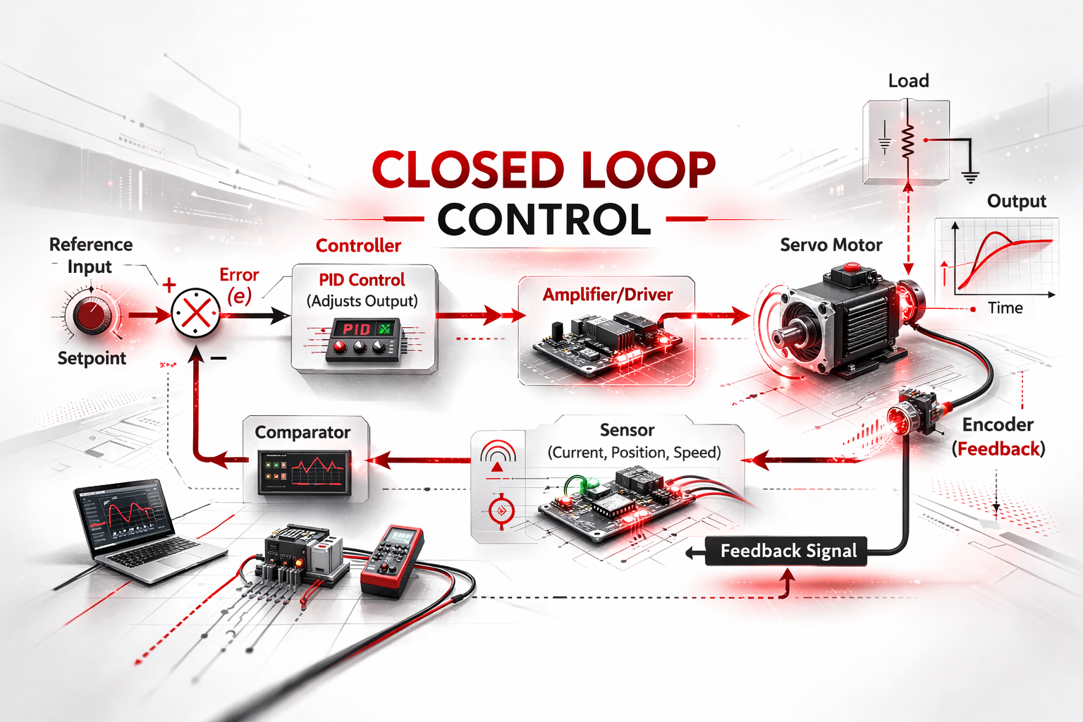
A closed-loop control system is a control system whose action depends on the measured output through a feedback path. This allows the system to automatically regulate a process variable to match a reference input (setpoint).
In a closed loop, a sensor or transducer measures the output (or a function of it). That measurement returns as a feedback signal, and the controller computes an error signal from the difference between the setpoint and the actual output.
The controller then drives the actuator to influence the plant/process and reduce that error. Because the loop continuously corrects itself, closed-loop control is also called feedback control, and it is the default choice when accuracy, repeatability, and disturbance rejection matter more than simplicity.
Why do closed-loop systems matter?
Closed-loop systems matter because feedback lets a controller correct disturbances and drift in real time, keeping performance stable even when the environment isn’t.
Loads change. Temperatures wander. Friction increases. Supply voltage sags. A well-designed closed loop detects these deviations and compensates, making the output repeatable and less sensitive to outside conditions.
That reliability is exactly why closed-loop control is everywhere in modern automation. Digital controllers—whether microcontrollers, PLCs, or the processors inside an ADVANCED Motion Controls servo drive—can read multiple sensors and coordinate outputs faster than any human operator.
Closed-Loop vs. Open-Loop Control
Closed-loop control uses feedback from the output to adjust the control action. Open-loop control does not. That one sentence is the whole difference—but it explains a lot.
An open-loop system follows a command schedule whether or not the output matches the target. For example, a basic heater might run for “10 minutes every hour.” It might work on a mild day, but it won’t adapt when the room is colder or a window is left open. A closed-loop system measures the actual temperature and runs the heater only until the setpoint is reached.
The Industrial Risk of Open-Loop
Zooming out from thermostats to machinery, the difference becomes critical. In open-loop motion control, the controller assumes the commanded move happened. If an axis binds, slips, stalls, or loses steps, the program keeps going anyway because there is no feedback saying, “we didn’t get there.”
This is where open-loop failure becomes a safety issue. The next tool move might be based on a position that only exists in software. This discrepancy can lead to crashed tooling, gouged parts, broken fixtures, and mechanical collisions.
Closed-loop control adds sensors and tuning effort, but it is the standard path to accuracy and robustness. If the load changes or an axis lags, the feedback signal shows the deviation and the controller corrects it—or triggers a fault before damage occurs.
How does a closed-loop control system work?
A closed-loop system works by measuring the output, comparing it to a setpoint, and driving corrective action based on the resulting error.
The key “thinking point” in the loop is the comparison element—often called a summing junction—where the setpoint and the feedback measurement are algebraically combined.
The canonical relationship is:
$$Error = Setpoint – Actual$$
- If the output drops below the setpoint, the error becomes positive, and the controller increases the input.
- If the output rises above the setpoint, the error flips sign, and the controller backs off.
The payoff is disturbance correction. If a disturbance pushes the output away from the target—like a sudden load increase on a motor—the sensor sees the deviation immediately, and the controller compensates until the output returns within bounds.
How is the feedback loop closed inside a servo drive?
In the context of motion control, the servo drive is the “brains + muscle” package. It reads feedback, computes error, and pushes torque until the error shrinks to zero.
At ADVANCED Motion Controls, we design our drives using a Nested Loop architecture. Most servo systems don’t run just one loop—they coordinate three, each focused on a different variable and time scale:
- Current (Torque) Loop (Innermost, Fastest): This loop controls the motor current to produce the commanded torque. It must be extremely fast to handle the electrical dynamics of the motor windings.
- Velocity Loop (Middle): This loop controls speed. It uses a speed estimate (often derived from encoder feedback) to command torque. If the load increases and speed drops, this loop commands more current to compensate.
- Position Loop (Outermost): This loop compares the commanded position to the measured position. It generates velocity commands to eliminate “following error.”
So how does the servo drive “push harder” when the load changes? It adjusts the average motor voltage and current delivered by the power stage, commonly through PWM (Pulse Width Modulation) switching.
If the axis slows under load, the feedback shows the speed drop, the error increases, and the drive responds by commanding more current (more torque) until the target speed is restored. This robustness is the primary advantage of servo control over stepper or open-loop systems.
What is Dual Loop Control?
Standard servo systems use a single feedback device (usually on the motor) for all three loops. However, in high-precision applications, Dual Loop Control offers a significant advantage.
Dual Loop Control uses two measurement points to control one axis:
- A Motor Encoder for the velocity loop (stability).
- A Load-Mounted Linear Scale for the position loop (accuracy).
Why split it?
Because the motor and the load are not always the same thing. Belts stretch, couplings twist, and gears have backlash. A motor encoder can report perfect rotation while the load is actually lagging behind due to mechanical compliance.
With Dual Loop Control, the inner velocity loop stays tight and smooth using the motor feedback, while the outer position loop closes on the linear scale. This ensures the controller keeps driving until the actual load reaches the target, not just the motor shaft.
Tuning a Closed-Loop System
Tuning is the process of selecting controller parameters (like P, I, and D gains) so the loop meets performance targets without going unstable.
- Define targets: Specify tolerances for steady-state error, overshoot, and settling time.
- Identify the plant: Understand what you are controlling (inertia, friction, resonance).
- Set initial gains: Start conservatively. High gains reduce error but increase the risk of oscillation.
- Validate: Test under worst-case loads and disturbances. A loop that is stable in the air might oscillate when coupled to a heavy load.
The biggest engineering risk in closed-loop control is instability. Too much gain or too much delay (latency) can cause the system to self-oscillate. Proper tuning finds the “Goldilocks” zone—stiff enough to reject disturbances, but damped enough to remain stable.
Conclusion
Closed-loop control is fundamentally simple: measure output, compute error, and correct input. Yet, that single idea enables the precision automation we rely on today—from thermal systems to multi-axis robotics.
While it comes with increased complexity in sensors and tuning, the benefits of accuracy, repeatability, and disturbance rejection make it indispensable. Whether you are tuning a PID loop or commissioning a multi-axis servo system, the principle remains the same: trust the feedback, but respect the physics.
The post What is Closed-Loop Control: The Foundation of Modern Automation appeared first on ADVANCED Motion Controls.
]]>The post Holiday Schedule 2025 appeared first on ADVANCED Motion Controls.
]]>To help you plan for the coming weeks, we are announcing our Holiday Schedule.
The last day of shipping for 2025 will be Tuesday, December 23.
Our facility will be closed Thursday, December 25 through Sunday, January 4.
Engineering, support, manufacturing, and sales will be unavailable during this time.
We will reopen Monday, January 5.

The post Holiday Schedule 2025 appeared first on ADVANCED Motion Controls.
]]>The post Find Us in Pittsburgh for Robotics & AI Discovery Day! appeared first on ADVANCED Motion Controls.
]]>
Pittsburgh Robotics Network’s annual Discovery Day is evolving – introducing Robotics & AI Discovery Day!
Explore the future of robotics and artificial intelligence at this newly expanded event designed for everyone from industry veterans to curious newcomers.
Join us for this free, public event and...
- Experience the latest breakthroughs in robotics and AI technology
- Watch live demonstrations of cutting-edge robotic and manufacturing systems
- Connect with professionals across all sectors of the robotics industry
- Discover innovative solutions to conquer your next automation challenge
We're also sponsoring a Happy Hour on the expo floor – Stop by our booth (#525) and pick up a drink ticket!
Don’t miss this celebration of innovation and collaboration – Register Today!
When?
Wednesday, November 5
9:00 AM - 6:00 PM
Where?
David L. Lawrence Convention Center
Booth #525
1000 Fort Duquesne Blvd
Pittsburgh, PA 15222
The post Find Us in Pittsburgh for Robotics & AI Discovery Day! appeared first on ADVANCED Motion Controls.
]]>The post Come See Us at RoboBusiness 2025! appeared first on ADVANCED Motion Controls.
]]>
ADVANCED Motion Controls is proud to be the official registration sponsor of RoboBusiness - the West Coast's premier robotics conference and expo!
This October, join us in Santa Clara, CA, where innovators, developers, integrators, and component manufacturers from across the robotics landscape will come together to shape the future of the industry.
Visit us at Booth 311 to browse our wide-range of high-performance servo drives firsthand and see how they bring advanced robotic systems to life.
Beyond the exhibit hall, RoboBusiness offers a packed agenda of expert-led panels, networking events, and the always-thrilling Pitchfire startup competition, where emerging companies unveil the next big breakthroughs in robotics.
Don’t miss this opportunity to connect, learn, and lead at the forefront of robotics innovation!
When?
Wednesday October 15
10:00 AM – 5:00 PM
Thursday October 16
10:00 AM – 3:00 PM
Where?
Santa Clara Convention Center
Booth 311
5001 Great American Parkway
Santa Clara, CA 95054
The post Come See Us at RoboBusiness 2025! appeared first on ADVANCED Motion Controls.
]]>The post What is a DC Servo Motor: Definition, Working Principle and Applications appeared first on ADVANCED Motion Controls.
]]>The controller continuously compares feedback to the target input and adjusts power to minimise error, ensuring accurate and consistent motion.
DC servo motors motors are widely used in robotics, CNC machinery, and automated manufacturing where high accuracy under variable load conditions is essential.
In this article, we will be lifting the lid on DC motor technology and examining how servo designs work, their components, performance characteristics, and the factors that determine their suitability for different applications.
How Do DC Servo Motors Work: What Is the Working Principle of a DC Servo Motor?
A DC servo motor operates on a closed-loop control principle. The system receives a command signal representing the desired position, speed, or torque.
The controller processes this signal and adjusts the voltage or current sent to the motor via the driver.
As the motor moves, the feedback device measures the actual output.
The controller continuously compares this measurement with the target signal and corrects any difference, known as the error.
How Does Feedback Enable Precision Control?
Feedback is the defining feature of a servo motor system. Common devices include incremental or absolute encoders for high-resolution position tracking, and potentiometers for lower-cost systems.
Feedback data allows the controller to maintain accuracy even under changing loads. It also enables features like quick reversal, variable acceleration, and precise holding torque without overshoot.
What Is the Transfer Function of a DC Servo Motor?
The transfer function is the mathematical relationship between the input command signal and the output motion.
It models how the motor, driver, and mechanical load respond to electrical inputs. In control theory terms, it is typically expressed as the
Laplace transform of the output over the input. Understanding the transfer function is essential for tuning control parameters such as proportional, integral, and derivative gains in a PID controller.
A well-defined transfer function ensures predictable, stable motion.
What Are the Components of a DC Servo System?
A DC servo motor is the core actuator in a larger servo system. For precise motion control, the motor must work together with several key components. Understanding the role of each part is essential.
- DC Servo Motor: This is the component that converts electrical energy into mechanical motion. It consists of the motor itself (which can be brushed or brushless) and an integrated feedback device, such as an encoder or resolver, that measures the motor’s actual position or speed.
- Servo Drive (or Amplifier): This is the “brain” of the system. A servo drive, like those manufactured by ADVANCED Motion Controls, receives a command signal from a main system controller (like a PLC or motion controller) and interprets the feedback from the servo motor. It then delivers the precise voltage and current needed to make the motor follow the command with minimal error.
- Power Source: This component supplies the electrical energy for both the servo drive and the motor.
How Does Gearbox Integration Affect DC Servo Motors?
Gearboxes modify a servo motor’s torque, speed, resolution, and overall efficiency.
They are available in several different types, as highlighted below:
- Spur Gearbox: Simple, efficient, and cost-effective, suited for moderate torque increases. Best for applications where size and cost are priorities but extreme torque multiplication is not required.
- Worm Gearbox: Provides high torque and self-locking capability, useful in holding applications. Less efficient due to higher friction and heat generation.
- Planetary Gearbox: High torque density in a compact form, with good efficiency. Well suited for precision automation and high-performance systems.
The correct gearbox type ensures the motor meets load, acceleration, and positioning requirements without oversizing the motor or consuming excessive power.
What Are the Types of DC Servo Motors?
DC servo motors are classified mainly into brushed and brushless designs.
Both use closed-loop control with feedback, but they differ in construction, efficiency, cost, and maintenance requirements.
Brushed DC Servo Motors
Brushed DC servo motors use a mechanical commutator and brushes to switch current in the armature windings.
They are simple to control, often needing only basic drive electronics, which keeps system cost low. Their design makes them a good fit for lower-speed applications or systems where up-front budget is the priority.
Pros
- Low initial cost
- Simple control electronics
- High starting torque
Cons
- Brushes wear out and require replacement
- Generates electrical noise and carbon dust
- Shorter service life compared to brushless
Brushless DC Servo Motors
Brushless DC servo motors use electronic commutation with a permanent magnet rotor and wound stator.
They require a dedicated controller but offer higher efficiency, longer life, and smoother operation. They are the preferred choice for high-performance automation, robotics, and continuous-duty applications.
Pros
- High efficiency
- Low maintenance
- Long operational life
- Quieter and smoother operation
Cons
- Higher initial cost
- Requires complex control electronics
- More difficult to service in the field
How Do You Choose the Right DC Servo Motor?
Selecting a DC servo motor starts with understanding the mechanical and control requirements of the application. The six most common factors include:
- Torque: Ensure the motor can deliver the required torque across the full speed range, accounting for peak demands.
- Speed: Match the motor’s maximum RPM to the needs of the mechanism, considering any gear reduction.
- Size and Weight: Fit the motor within available space without exceeding weight constraints, especially in mobile or aerial systems.
- Load Characteristics: Identify whether the load is constant, variable, or includes sudden changes that require high acceleration torque.
- Operating Environment: Consider temperature extremes, dust, moisture, and potential contamination that may require sealing or IP-rated housings.
- Control Requirements: Determine if the application needs basic positioning or precise multi-axis synchronisation, which will influence controller complexity.
How Are DC Servo Motors Controlled and Operated?
DC servo motors operate within a closed-loop control system that continuously compares actual position or speed to a target value. The controller adjusts motor input based on feedback to minimise error and maintain performance.
How Is Speed and Position Control Achieved?
Speed and position control are most often implemented using PWM (pulse-width modulation). PWM varies the effective voltage applied to the motor by adjusting the duty cycle of the drive signal.
The controller uses feedback from an encoder or potentiometer to adjust the PWM signal in real time.
For precise positioning, a PID (proportional-integral-derivative) control algorithm is often used, tuning the response to avoid overshoot and maintain stability.
How Can DC Servo Motors Be Interfaced with Microcontrollers?
Microcontrollers such as Arduino, STM32, or Raspberry Pi can control DC servo motors through dedicated motor driver boards or H-bridge circuits. The microcontroller outputs a PWM signal to the driver, which then powers the motor accordingly.
Feedback is read through digital or analog inputs, depending on whether an encoder or potentiometer is used.
Basic code typically involves setting PWM frequency, adjusting duty cycle based on feedback, and implementing control logic to reach and hold the target position or speed.
What Braking Methods Are Used in DC Servo Motors?
DC servo motors can be stopped or slowed using several braking techniques, with dynamic and regenerative braking being the most common.
Dynamic Braking
In dynamic braking, the motor terminals are connected to a resistive load when braking is commanded. The motor acts as a generator, converting kinetic energy from the load into electrical energy that is dissipated as heat in the resistor.
This method is simple, reliable, and provides rapid deceleration, but it wastes the recovered energy.
Regenerative Braking
Regenerative braking also uses the motor as a generator, but instead of dissipating the energy as heat, the generated electrical energy is fed back into the power supply or battery.
This improves energy efficiency, especially in applications with frequent starts and stops. Regenerative braking requires compatible drive electronics and is often used in high-efficiency automation systems, robotics, and electric vehicles.
What Are the Electrical Characteristics and Performance Specifications of DC Servo Motors?
DC servo motors are defined by both electrical and mechanical ratings. Key electrical characteristics include operating voltage, continuous and peak current limits, and power rating.
Mechanical specifications cover rated torque, maximum torque, speed range, and encoder resolution.
Thermal limits such as maximum winding temperature are also critical, as exceeding them can shorten service life or cause permanent damage.
These specifications together determine the motor’s suitability for a given load, duty cycle, and control system.
Voltage, Current, and RPM Ratings
The rated voltage determines the speed capability of the motor, while the current rating defines how much torque it can produce. Higher voltage generally allows higher RPM, assuming the load and driver can support it.
Continuous current ratings indicate the current the motor can sustain without overheating.
Peak current ratings define the short bursts it can handle for acceleration or sudden load changes.
For example, a motor rated at 24 V, 3 A continuous, and 9 A peak can deliver much higher torque during short acceleration phases than in steady-state running.
Speed-Torque Characteristics
DC servo motors typically have a linear relationship between torque and speed. At no load, the motor runs at its maximum speed.
As the load increases, torque demand rises and speed drops proportionally until it reaches the stall torque point, where speed is zero. Continuous operation should remain within the motor’s rated torque curve to prevent overheating and excessive wear.
Stall conditions should be avoided except for very short, controlled periods, as they cause rapid temperature rise and can overload the drive electronics.
Understanding this relationship is essential for sizing a motor correctly and ensuring stable performance across varying loads.
Position Memory and Precision
Standard DC servo motors do not inherently retain position memory when powered off. Position control accuracy depends on the feedback device and controller.
High-resolution encoders enable repeatable positioning to within fractions of a degree or microns in linear systems, provided backlash and mechanical compliance are minimised. If position retention after power loss is required, the system must use battery-backed encoders or absolute feedback devices.
How Are DC Servo Motor Parameters Estimated?
For advanced system design, estimating parameters allows engineers to model and predict performance before hardware is installed. This involves measuring electrical constants such as armature resistance and inductance, as well as mechanical constants like inertia and friction.
These values feed into motor models for tuning control loops and simulating performance under different load scenarios.
What Techniques Are Used for Parameter Estimation?
Common techniques include no-load and locked-rotor tests to determine back EMF constants, torque constants, and resistance values.
Step-response analysis is used to characterise dynamic behaviour for speed and position control. System identification methods can be applied, where known inputs are applied and outputs are recorded, then fitted to a mathematical model.
Advanced setups may use dedicated motor analysers or dynamometers for high-accuracy measurements.
Where Are DC Servo Motors Commonly Used?
DC servo motors are found anywhere precise, responsive motion control is required. Their combination of accuracy, torque control, and adaptability makes them valuable across industrial, commercial, and consumer applications.
Industrial Automation
In manufacturing, DC servo motors power CNC machinery, conveyor systems, and automated assembly lines. They enable precise positioning for cutting tools, smooth movement in pick-and-place systems, and accurate control of high-speed packaging equipment.
In factory robotics, they deliver the responsiveness needed for multi-axis motion and synchronized operations.
Robotics and Mechatronics
In robotics, DC servo motors control joint movement in robotic arms, maintain stability in mobile robots, and drive actuation in grippers. In aerial platforms such as drones, they are used for camera gimbals and fine mechanical adjustments.
Mechatronic systems use them in test rigs, inspection equipment, and laboratory instruments where small, precise movements are critical.
Consumer Electronics and Everyday Uses
In consumer devices, DC servo motors are used in autofocus and zoom mechanisms in cameras, paper feed systems in printers, and optical drive mechanisms.
Hobby electronics projects use miniature servo motors for robotics kits, RC vehicles, and model control systems where compact size and precise motion are important.
Are DC servo motors expensive?
DC servo motors generally cost more than standard DC motors or open-loop stepper motors. The higher price comes from their precision control capabilities, integrated feedback systems, and the need for compatible drive electronics.
Whether they are “expensive” depends on the application’s requirements and the total system cost over its service life.
Factors Influencing the Cost of DC Servo Motors
- Motor Type: Brushless DC servo motors are typically more expensive than brushed types due to their higher efficiency, longer lifespan, and advanced electronic commutation.
- Power and Torque Rating: Larger motors with higher torque output or higher continuous power ratings cost more due to increased material use and manufacturing complexity.
- Feedback Device: Motors equipped with high-resolution encoders, absolute encoders, or resolvers add significantly to the price compared to units with basic potentiometers or lower-resolution devices.
- Controller Requirements: A servo motor must be paired with a matching driver or servo amplifier. High-performance controllers with features like advanced motion profiles, multi-axis synchronization, or fieldbus communication increase the overall system cost.
- Build Quality and Materials: Motors built for industrial or aerospace environments use higher-grade materials, precision bearings, and protective housings that raise the price.
- Customization: Special shaft designs, gear integrations, or unique mounting requirements add to manufacturing cost.
- Supplier and Brand: Established brands with proven reliability and long-term support often command higher prices than generic imports.
How Should DC Servo Motors Be Maintained?
Proper maintenance keeps DC servo motors running at peak performance and reduces downtime from unexpected failures.
Maintenance involves regular inspection, cleaning, and component replacement, along with identifying and resolving operational issues before they escalate.
- Cleaning: Keep the motor and surrounding area free from dust, debris, and moisture. Compressed air can be used for external cleaning, but avoid directing high pressure into bearings or seals.
- Inspection: Regularly check electrical connections, mounting hardware, and feedback device alignment. Look for signs of wear or damage to cables and connectors.
- Lubrication: If the motor has serviceable bearings, lubricate them as recommended by the manufacturer. Many modern units have sealed bearings that require no lubrication.
- Brush Replacement (for brushed DC servos): Monitor brush length and replace them before they wear below the manufacturer’s specified limit. Clean the commutator to remove carbon buildup.
What Are Common Problems in DC Servo motors and How to Fix Them?
- Overheating: Caused by excessive load, poor ventilation, or incorrect tuning. Reduce the mechanical load, improve airflow around the motor, or adjust controller settings to prevent continuous high current draw.
- Wiring Faults: Broken, loose, or corroded connections can cause erratic operation or complete failure. Inspect all cables and connectors, replace damaged sections, and use proper strain relief.
- Control Errors: Position overshoot, oscillation, or drift can result from encoder misalignment, electrical noise, or poor PID tuning. Realign feedback devices, improve cable shielding, and retune the controller parameters.
How Can Failures Be Prevented?
- Keep the motor operating within its rated torque, speed, and duty cycle.
- Maintain adequate cooling through ventilation or heat sinking.
- Protect the motor from dust, moisture, and corrosive substances with sealed housings or covers.
- Replace brushes in brushed servo motors before they wear out completely.
Periodically recalibrate feedback devices and verify that control parameters are still optimal. - Perform routine inspections to catch small issues before they lead to major failures.
What Are the Environmental and Operating Considerations for DC Servo Motors?
The operating environment has a direct impact on the performance and lifespan of a DC servo motor.
In applications where dust, moisture, or chemical exposure is present, motors should have an appropriate IP (Ingress Protection) rating to prevent contamination of internal components.
Sealed housings, gaskets, and corrosion-resistant materials are essential in harsh or outdoor installations.
Temperature limits are another critical factor; most DC servo motors are rated for operation within a specified ambient range, and exceeding these limits can lead to overheating, lubricant breakdown, or electronic failure.
In extreme heat or cold, additional measures such as forced cooling, heaters, or insulated enclosures may be required.
For outdoor or heavy industrial use, selecting a motor designed with enhanced sealing, reinforced construction, and suitable coatings ensures reliable performance despite exposure to vibration, debris, or weather conditions.
How Do DC Servo Motors Differ from AC Servo Motors?
While both DC and AC servo motors provide high-performance motion control, they differ in their construction, control methods, and ideal applications.
DC servo motors run on direct current and are known for their high starting torque and simple control principles. This makes them excellent for applications requiring rapid acceleration and precise positioning at variable speeds, such as robotics and battery-powered devices.
An AC servo motor operates on alternating current and is generally favored for high-power, continuous-duty industrial applications where maximum efficiency and power density are critical. Since they are almost always brushless, they require very little maintenance.
For a more technical distinction, it’s helpful to compare a Brushless DC (BLDC) servo with what is often called an AC servo (typically a Permanent Magnet Synchronous Motor, or PMSM). These two types of motors are structurally very similar. The primary difference lies in the drive technology and commutation method:
- BLDC servo systems often use a simpler trapezoidal commutation, which energizes the motor windings in a stepped, block-like pattern.
- AC servo systems typically use sinusoidal commutation, which provides a smooth, continuously varying current to the windings. This method results in smoother motion with less torque ripple, making it ideal for the most demanding high-performance applications.
Conclusion
DC servo motors offer smooth speed regulation and fast torque delivery, making them ideal for applications such as robotics, CNC machinery, and automated production lines.
Compared to AC servo motors, DC designs can be easier to control at low speeds, offer more predictable performance in portable or battery-powered setups, and suit projects where simpler drive electronics are an advantage.
Choosing between brushed and brushless versions comes down to balancing performance needs, budget, and maintenance expectations. With the right match and proper upkeep, DC servo motors can deliver years of dependable, repeatable operation in both industrial and high-performance environments.
FAQs
1. Can DC servo motors run continuously?
Yes, DC servo motors can run continuously if they are properly rated for the duty cycle and cooling requirements of the application. Continuous-duty models are designed to handle sustained operation without overheating, but correct load sizing and adequate ventilation are essential to avoid premature wear.
2. Are DC servo motors suitable for outdoor environments?
Yes, but only if they have the correct environmental protection. Motors intended for outdoor use should have a high IP rating to resist dust and moisture, corrosion-resistant materials, and sealing against contaminants. Additional measures such as weatherproof enclosures or protective coatings may be required in harsh conditions.
The post What is a DC Servo Motor: Definition, Working Principle and Applications appeared first on ADVANCED Motion Controls.
]]>The post Auto-Tuning Tutorial for FlexPro Servo Drives appeared first on ADVANCED Motion Controls.
]]>Our ACE (AMC Configuration Environment) software features automatic loop tuning for the current, velocity, and position loops on select FlexPro servo drives. Auto-tuning saves users time and effort by providing sufficient loop tuning for most applications and a good starting point for those that require more specialization.
The video below will walk you through the auto-tuning process.
Auto-tuning is available for CANopen and RS-485/232 FlexPro models. Support for EtherCAT and EtherNet/IP models is on the way.
The post Auto-Tuning Tutorial for FlexPro Servo Drives appeared first on ADVANCED Motion Controls.
]]>The post Mechanical Servo Motors Failures and Faults appeared first on ADVANCED Motion Controls.
]]>But even the most reliable systems have their limits. Push those too far, skip routine checks, or operate in less-than-ideal conditions, and you’ll start seeing servo motor faults creep in, sometimes gradually, sometimes with a (literal) bang.
This article explores the most common servo motor faults, how they develop, and what you can do to catch them before they cause serious damage.
What Are the Common Symptoms of a Bad Servo Motor?
Servo motors don’t usually fail without warning, but when they do, it’s rarely subtle. Spotting issues early can save you from unexpected downtime and avoid more expensive repairs down the line. Here’s what to look out for, and why these servo motor faults crop up:
- Strange Noises: Grinding, buzzing, or clicking sounds can mean anything from worn bearings to electrical glitches or internal mechanical wear.
- Vibration: Excessive or sudden vibration usually hints at misalignment, a rotor issue, or something coming loose inside the housing.
- Overheating: If the motor runs hotter than expected, you could be dealing with excessive load, poor airflow, or deeper electrical problems.
- Erratic Operation: Random speed changes, stuttering, or sync loss often point to encoder faults, bad wiring, or miscommunication with the control system.
- Loss of Accuracy and Efficiency: Struggling to hold position or burning more power than usual? That’s often a feedback loop issue, mechanical drag, or encoder wear.
- Control System Errors: If the control system throws faults it’s likely flagging load issues, overheating, or broken feedback links.
Common Servo Motor Faults
This section covers the usual suspects when servo motors go sideways.
For each fault, we’ll break down what causes it, how to spot it early, and what you can do to prevent (or at least contain) the damage before it takes down your whole system.
Overheating
Overheating is one of the more damaging servo motor faults. Excessive heat can fry windings, break down insulation, and tank overall performance if left unchecked.
Why This Problem Occurs
- High Ambient Temperatures: Running motors in hot environments pushes them past safe thermal limits.
- Blocked Cooling Paths: Dust, debris, or buildup around the motor housing can choke airflow and trap heat.
- Long Duty Cycles: Continuous operation without enough rest gives heat no time to dissipate.
- Poor Ventilation: Tight spaces with restricted airflow don’t give the motor room to breathe.
- Worn Internals: Aging parts generate more friction, which means more heat.
Symptoms and Signs
- Excess Heat: Noticeable heat buildup during or after operation indicates potential overheating.
- Discoloration: Discolored components may suggest excessive temperature exposure.
- Burnt Smell: A burnt odor often indicates insulation damage or excessive heating of components.
Detection Methods
- Temperature Sensors: Real-time monitoring of the motor’s heat levels.
- Thermal Imaging: Detects heat hotspots and uneven distribution.
- Manual Inspection: Identify signs of overheating through physical inspection.
Prevention and Maintenance Tips
- Proper Ventilation: Ensure motors are operated in well-ventilated environments.
- Climate-Controlled Environments: Operate motors in controlled temperature and humidity settings where feasible.
- Regular Maintenance: Clean cooling systems and replace worn parts to ensure consistent performance.
- Cooling Fans: Install additional fans to improve airflow.
- Failsafe Mechanisms: Use systems that trigger shutoffs when safe temperature limits are exceeded.
Bearing Failure
Bearing failure is one of the more common servo motor faults. When bearings go, friction goes up, noise kicks in, and before long, the motor starts struggling. Since bearings keep the shaft turning smoothly, any trouble here can throw off efficiency and cause bigger performance issues down the line.
Why This Problem Occurs
- Normal Wear and Tear: Bearings degrade over time due to continuous operation and load cycles.
- Improper Installation or Reinstallation: Misalignment from incorrect installation accelerates bearing wear and causes inefficiency.
- Contamination: Dirt, dust, and other particles can infiltrate the bearing system, leading to abrasive wear and failure.
- Overloading: Excessive loads beyond design limits cause stress and early bearing degradation.
- Poor Lubrication: Insufficient or degraded lubrication increases friction, resulting in faster wear.
Symptoms and Signs
- Abnormal Sounds: Growling, squeaking, or screeching noises during operation indicate bearing distress.
- Increased Vibration: Excessive vibrations often point to bearing misalignment or wear.
- Heat Generation: Overheated bearings suggest friction and potential damage.
Detection Methods
- Vibration Sensors: Monitor and detect early signs of abnormal movement patterns in the motor.
- Manual Inspection: Regular checks for noises, heat, or wear signs.
- Temperature Monitoring: Continuously track heat levels to identify overheating.
Prevention and Maintenance Tips
- Routine Checking and Replacing Bearings: Schedule inspections and replace bearings as needed.
- Use Vibration Sensors: Early detection can prolong motor lifespan.
- Proper Installation Techniques: Ensure alignment during bearing installation.
- Keep Bearings Clean: Minimize contamination by regularly cleaning motor components.
- Lubrication: Apply proper lubrication to reduce wear and friction.
Brake Failure
Brake failure in servo motors can lead to positioning errors and unexpected downtime. Since the brake’s job is to hold position, it’s prone to wear, especially if it’s used too often, or forced to handle frequent or emergency stops.
Why This Problem Occurs
- Repetitive Stopping and E-Stops: Servo brakes are not typically designed for frequent stops or repeated emergency stops, leading to accelerated wear.
- Contamination: Dust, oil, and other contaminants can impair brake function and lead to performance degradation.
- Enclosed Design: Many servo motors with high protection ratings, like IP65, house brakes internally, complicating inspections and replacements.
Symptoms and Signs
- Unusual Noises: Grinding or squeaking noises during motor operation may indicate brake problems.
- Erratic Operation: Irregular motor movement or control issues often point to brake malfunctions.
- Heat Generation: Excessive heat around the brake area suggests impending brake failure.
Detection Methods
- Visual Inspection: Routine checks to detect signs of wear, contamination, or damage.
- Performance Testing: Evaluating brake performance under load conditions to identify inconsistencies.
- Thermal Imaging: Thermal cameras help detect unusual heat distribution around the brake system.
Prevention and Maintenance Tips
- Engage Brakes Correctly: Only engage brakes when the motor is at a standstill to minimize dynamic wear.
- Use Specialized Brakes for Frequent Stops: For applications requiring repeated stops, use brakes designed for dynamic stopping, such as spring-set or double C-face brakes.
- Regular Inspection: Schedule routine inspections to monitor for wear and contamination.
- Maintain Clean Environments: Keep the operating area free from contaminants like dust and oil.
- Proper Installation: Follow correct installation procedures to ensure brake function and longevity.
Servo Motor Fails to Turn
If a servo motor won’t turn, you’ve got a showstopper on your hands. Whether it’s the motor, the drive, or the controller, something in the signal chain is broken. The result is downtime, plain and simple.
Why This Problem Occurs
- Controller Issues:
- DAC Output Problems: If the Digital-Analog Converter (DAC) output is incorrect, the motor may not turn.
- Outdated Software: Using incorrect or outdated software can disrupt motor function.
- Drive Issues:
- Drive Efficiency: Inefficient drive operation can impair motor performance.
- Drive Failure: A failing drive can prevent the motor from turning.
Symptoms and Signs
- Motor Inactivity: The motor fails to move as expected.
- Control System Errors: Error messages or faults appear in the control system.
- Lack of Response: The motor does not react to control inputs.
Detection Methods
- Control System Diagnostics: Check the controller and drive for faults using diagnostic tools.
- Manual Testing: Test motor response to direct control inputs.
- Software Analysis: Examine control software for errors or outdated code.
Prevention and Maintenance Tips
- Regular Software Updates:
- Keep Software Current: Regularly update control software to avoid compatibility issues.
- Drive Maintenance:
- Routine Self-Tests: Periodically perform self-tests on the drive.
- Timely Repairs: Address drive issues promptly.
- Controller Maintenance:
- Verify Settings: Regularly check settings in the controller’s software/hardware.
- Check Parameters: Ensure gain, velocity, and acceleration profiles are correct.
Servo Motor Shuts Off At High Speeds
If a servo motor cuts out at high or full speed, it usually means something’s off with the overload protection, cooling, or electrical system. Either way, you’re headed for downtime if it’s not addressed.
Why This Problem Occurs
- Defective Overload Protection System: A malfunctioning overload protection system may prematurely shut down the motor when it’s under excessive load.
- Rapid Overheating: Operating at high speeds without sufficient cooling leads to internal component damage and shutdown.
- Inadequate Bearings: Poorly maintained or improperly installed bearings contribute to overheating and motor failure.
- Blown Fuses or Old Fuses: Outdated or blown fuses disrupt the electrical flow, causing shutdowns.
- Bad Capacitors: Faulty capacitors interfere with the motor’s electrical functions, leading to shutdowns.
- RPM Meter Malfunction: Inaccurate RPM readings can cause incorrect adjustments and force the motor to shut off.
- Voltage Drops or Poor Wiring: Electrical instability or faulty wiring can cause erratic motor operation.
Symptoms and Signs
- Motor Shuts Off Unexpectedly: The motor stops after reaching high speeds.
- Overheating: The motor becomes unusually hot.
- Unusual Noises: Grinding or whining noises from the motor.
- Inconsistent Performance: Fluctuating motor speed or unexpected shutdowns at high speeds.
Detection Methods
- Thermal Imaging: Detect overheating hotspots in the motor.
- Performance Monitoring: Track motor performance for signs of overloading or overheating.
- Visual Inspection: Look for signs of physical damage or overheating.
- Electrical Testing: Use a multimeter to check for issues like blown fuses or damaged capacitors.
Prevention and Maintenance Tips
- Regular Maintenance: Conduct routine checks to ensure proper operation of all components.
- Cooling Solutions: Install additional cooling devices like fans or heat sinks to prevent overheating.
- Electrical Inspections: Regularly inspect wiring, fuses, and capacitors for wear or damage.
- RPM Meter Calibration: Calibrate the RPM meter periodically to maintain accurate speed readings.
Broken Motor Shaft
A broken shaft is about as bad as it gets—it stops the motor cold and can take down anything it’s connected to. It usually comes from mechanical stress, misalignment, or overload, and if it’s not caught early, the damage spreads fast.
Why This Problem Occurs
- Inadequate Mechanical Design: When the shaft is not designed to handle excessive radial loading forces, it can break under stress, leading to motor failure.
- Stuck Load or Severe Overload: If the motor faces a momentary overload or a stuck load, the shaft experiences an abrupt increase in force, which can cause it to fail.
- Misalignment During Assembly: Improper alignment between the motor and connected components creates uneven stress on the shaft, eventually leading to fractures.
Symptoms and Signs
- Loss of Motor Torque: A broken or damaged shaft results in the loss of motor power, causing the motor to fail to transmit torque effectively.
- Grinding or Abnormal Noise During Motor Operation: Unusual sounds, such as grinding, can indicate a mechanical issue with the shaft.
- Unresponsive Motor Even When Powered: The motor may fail to operate at all, even though electrical power is supplied, due to a broken shaft.
Detection Methods
- Visual Inspection of the Motor Shaft and Connected Components: Inspect the shaft for any visible cracks, deformation, or misalignment.
- Torque Monitoring During Operation: Monitor the motor’s torque output to identify any sudden drops that could indicate a shaft failure.
- Vibration Analysis to Detect Imbalances or Misalignments: Vibration sensors can help identify abnormal patterns that suggest shaft issues, such as imbalance or misalignment.
Prevention and Maintenance Tips
- Design Motors to Handle Expected Load Forces: Ensure the motor and shaft are designed to accommodate the maximum expected load to prevent overloading.
- Monitor Load Side Operations for Excessive Stress: Regularly check the load side of the motor to ensure it is not experiencing forces beyond its designed capacity.
- Ensure Precision Alignment During Assembly: Use precise alignment methods during installation to prevent misalignment that could lead to shaft failure.
Lubrication Issues
When lubrication breaks down, friction ramps up, heat builds, and performance takes a hit. Keep the moving parts properly greased, or you’re asking for wear, inefficiency, and eventually, motor failure.
Why This Problem Occurs
- Inadequate Lubrication: Increases friction, causing wear and overheating.
- Contamination: Dirt and debris degrade lubricant quality, raising friction and wear.
- Improper Lubricant: Using incompatible types can reduce effectiveness and damage components.
Symptoms and Signs
- Unusual Noise or Vibration During Operation: Insufficient or degraded lubrication leads to increased friction, which often manifests as grinding or unusual noises and vibrations.
- Overheating Due to Friction: Without proper lubrication, friction increases, causing the motor to overheat, which can further damage the components.
- Decreased Motor Performance: Increased friction and heat result in reduced efficiency, causing the motor to operate sluggishly or erratically.
Detection Methods
- Visual Inspection for Signs of Wear or Noise: Inspect the motor and surrounding components for visible wear, unusual noise, or signs of lubricant leakage.
- Monitor Motor Temperature for Overheating: Continuously monitor the motor’s temperature to detect abnormal rises that could indicate insufficient lubrication or excessive friction.
- Performance Analysis to Spot Inefficiencies: Regularly assess the motor’s performance and efficiency to identify signs of friction-related inefficiencies, such as decreased output or increased energy consumption.
Prevention and Maintenance Tips
- Implement a Routine Lubrication Schedule: Set a regular schedule to lubricate moving parts, ensuring they remain adequately lubricated and free of contaminants.
- Use the Appropriate Lubricant for the Motor: Always choose the right lubricant for your specific motor model and operating conditions to ensure optimal performance and protection.
- Seal the Motor to Prevent Contamination: Use seals and protective covers to prevent contaminants from entering the motor and affecting the lubricant’s quality and function.
Servo Motor Faults Ranked by Severity
As implied in the intro, not all faults are equal. Some faults can be catastrophic, resulting in immediate system failure, while others have a more gradual negative effect on system performance. In any case, an ounce of prevention is worth more than a pound of cure, so if you notice anything amiss with your servo motor hardware, then don’t delay – get it fixed, ASAP.
| Fault | Severity (1-5) | Consequences |
| Broken Motor Shaft | 5 | Immediate, catastrophic failure, total system downtime, potential collateral damage. |
| Servo Motor Fails to Turn | 5 | Complete operational halt, productivity loss, potentially costly diagnostics and repairs |
| Servo Motor Shuts Off At High Speeds | 4 | Unexpected interruptions, potential internal damage, risk of repeated shutdowns, operational instability |
| Bearing Failure | 4 | Increased friction, overheating, mechanical wear, significant vibration, reduced efficiency, motor damage |
| Overheating | 4 | Insulation damage, reduced efficiency, increased downtime, risk of irreversible damage, higher maintenance costs |
| Brake Failure | 3 | Reduced positioning accuracy, compromised operational safety, risk of unplanned movement, increased cycle times |
| Lubrication Issues | 2 | Increased friction, overheating, gradual performance reduction, accelerated component wear |
| Contamination | 2 | Progressive efficiency loss, overheating, corrosion, increased maintenance costs, gradual component damage |
Severity Rating Explanation:
- 5: Catastrophic failure with immediate downtime
- 4: Severe impact, significant damage risk, urgent corrective action required
- 3: Moderate impact, progressive damage, noticeable performance degradation
- 2: Mild impact, gradual degradation over extended periods
- 1: Negligible impact, easily manageable
Should You Repair or Replace a Failed Servo Motor?
The decision comes down to cost, downtime, motor age, parts availability, and upgrade plans.
Replacement is usually better if repair costs hit 50–70% of a new motor’s price, or if downtime hurts productivity. It’s also the smarter choice for older motors with frequent issues, hard-to-find parts, or poor post-repair performance.
Warranty coverage can tip the balance by reducing costs and making the choice clearer.
How Long Should a Servo Motor Last?
Servo motors typically have a lifespan ranging between 20,000 and 30,000 operating hours under standard conditions. This estimate depends on factors such as usage patterns, maintenance quality, and environmental conditions.
For more detailed insights on servo motor longevity and best practices to ensure optimal lifespan, see the information from Advanced Motion Controls.
Conclusion
Servo motors deliver precision, speed, and reliability, but issues like overheating, mechanical faults, and environmental factors can compromise performance.
Installing the hardware properly in the first place, in a clean environment is a good way to start a servo’s operational life.
Consistent monitoring, smart diagnostics, and a clean, stable environment are key to keeping servo systems running smoothly once operational.
Early detection of faults with tools such as temperature sensors and vibration analyzers can also help prevent damage and downtime once the system is up and running.
As the saying goes, early action beats late regret, so deal with servo motor issues before they turn serious. Because when a servo fails mid-cycle, the only thing moving fast will be your stress levels.
The post Mechanical Servo Motors Failures and Faults appeared first on ADVANCED Motion Controls.
]]>The post What is an AC Servo Motor: Definition, Working Principle, Characteristics and Price appeared first on ADVANCED Motion Controls.
]]>In this article, we’ll focus in detail on the mechanism of an AC servo motor, its parts and functions, and different types of AC servo motors including its application.
What is an AC Servo Motor?
An AC servo motor is a specialized servo motor type that uses alternating current (AC) to produce precise motion control. These motors are known for their high efficiency and performance in applications requiring accurate positioning, speed, and torque control.
The working principle of an AC servo motor involves converting AC electrical energy into mechanical energy through the interaction of a rotating magnetic field and a stationary stator.
The stator, which contains the motor windings, generates the magnetic field, while the rotor, connected to the output shaft, rotates in response to this field. The system typically includes a feedback mechanism to ensure precise control and adjustments.
How is an AC Servo Motor Different from a Normal AC Motor?
An AC servo motor differs from standard AC motors primarily in its ability to provide precise control over motion parameters such as position, speed, and torque.
While normal AC motors are designed for continuous operation at a constant speed, AC servo motors are optimized for dynamic performance and can rapidly respond to control signals. This makes them ideal for applications requiring high precision and quick adjustments.
The four main differences are:
- Feedback Mechanism: AC servo motors incorporate feedback devices like encoders or resolvers to monitor and adjust the motor’s performance in real-time. This ensures accurate control and positioning.
- Control System: These motors use sophisticated control systems, including servo drives, to manage the power supply and modulate the motor’s operation. This allows for precise regulation of speed and torque.
- Construction: AC servo motors are built with higher quality materials and tighter tolerances compared to standard AC motors. This enhances their performance and reliability in demanding applications.
- Torque and Speed Characteristics: AC servo motors are designed to provide high torque at low speeds and maintain consistent performance across a wide speed range. Normal AC motors typically deliver optimal performance at a single speed.
How Have AC Servo Motors Developed Historically?
AC servo motors have seen significant advancements since their inception, evolving through numerous technological milestones.
Initially, servo motors were basic devices used primarily for rudimentary positioning tasks in industrial applications.
Early versions lacked the precision and efficiency of modern AC servo motors. However, the development of feedback systems such as encoders and resolvers marked a speedy advancement, enabling higher accuracy and control.
In the mid-20th century, the introduction of digital control systems and microprocessors revolutionized servo motor technology. This era saw the integration of closed-loop control systems, which significantly improved the performance and reliability of AC servo motors. These systems continuously monitored the motor’s output and made real-time adjustments to maintain desired performance levels.
The 1980s and 1990s brought further advancements with the advent of brushless AC servo motors. These motors, characterized by their reduced maintenance needs and higher efficiency, quickly became the industry standard. The use of permanent magnets and sophisticated electronic controls allowed for more compact and powerful designs.
In recent years, the integration of advanced materials and manufacturing techniques has pushed the boundaries of what AC servo motors can achieve. Modern AC servo motors boast enhanced torque density, faster response times, and greater overall efficiency. The use of high-performance processors and advanced algorithms has further refined their operation, making them indispensable in applications requiring precise motion control.
How Does an AC Servo Motor Work?
An AC servo motor operates by converting electrical energy into mechanical motion, using a combination of stator and rotor components to achieve this transformation. The stator, equipped with windings, generates a rotating magnetic field when alternating current (AC) is applied. This magnetic field interacts with the rotor, which contains permanent magnets or windings, causing it to rotate.
The operation of an AC servo motor involves five critical steps:
- Power Input: The motor receives an AC input from a power source. This input is controlled by a servo drive, which regulates the voltage and current supplied to the motor.
- Magnetic Field Generation: The stator windings produce a rotating magnetic field when energized by the AC supply. The frequency and phase of the AC input determine the speed and direction of this field.
- Rotor Interaction: The rotating magnetic field induces a force in the rotor, causing it to turn. The rotor’s design, often incorporating permanent magnets or conductive windings, ensures efficient interaction with the magnetic field.
- Feedback System: An integral part of the AC servo motor is the feedback mechanism, typically an encoder or resolver. This system continuously monitors the rotor’s position, speed, and torque.
- Control Adjustments: The feedback data is sent to the servo drive, which adjusts the input parameters to maintain the desired motor performance. This closed-loop control ensures precise positioning and speed regulation.
How is an AC Servo Motor Constructed?
AC servo motors are composed of several key components that work together to provide precise motion control. Here, we will break down the primary parts of an AC servo motor and their respective functions.
Stator
The stator is the stationary part of the motor that houses the windings. These windings are typically made of copper and are arranged in a specific pattern to generate a rotating magnetic field when an alternating current (AC) passes through them.
This magnetic field is essential for inducing the motion of the rotor. The stator’s design and construction significantly influence the motor’s efficiency and performance. In high-quality AC servo motors, the stator windings are meticulously crafted to minimize losses and maximize magnetic flux.
- Material: The windings are usually made of copper for its excellent electrical conductivity.
- Function: Generates a rotating magnetic field to drive the rotor.
- Design: The pattern and placement of the windings determine the motor’s efficiency and performance.
Rotor
The rotor is the rotating part of the motor, which turns in response to the magnetic field generated by the stator. It typically contains permanent magnets or conductive windings that interact with the stator’s magnetic field.
The rotor’s design can vary depending on the type of AC servo motor, such as synchronous or asynchronous. In synchronous motors, the rotor includes permanent magnets that maintain a constant magnetic field, while in asynchronous (induction) motors, the rotor windings induce a magnetic field in response to the stator’s rotating field.
- Material: Can include permanent magnets or conductive windings.
- Function: Rotates to produce mechanical motion.
- Types: Synchronous rotors use permanent magnets, while asynchronous rotors use induced magnetic fields.
Feedback Device (Encoder or Resolver)
The feedback device is a critical component in an AC servo motor, providing real-time data on the motor’s position, speed, and direction. There are two primary types of feedback devices used in AC servo motors: encoders and resolvers.
Encoder:
- Function: An encoder measures the rotational position and speed of the motor shaft. It converts the mechanical position of the shaft into an electronic signal that can be processed by the control system.
- Types: There are two main types of encoders used in AC servo motors: incremental and absolute. Incremental encoders provide relative position information, while absolute encoders provide a unique position value for each shaft angle.
- Advantages: Encoders offer high resolution and accuracy, making them ideal for applications requiring precise motion control.
Resolver:
- Function: A resolver is an analog device that provides continuous position feedback. It operates by inducing a voltage in secondary windings proportional to the shaft angle.
- Advantages: Resolvers are robust and can operate in harsh environments with high temperatures, vibration, and electrical noise. They provide reliable feedback even in challenging conditions.
- Applications: Resolvers are commonly used in industrial applications where durability and reliability are critical.
Drive (Servo Drive)
The servo drive, also known as the servo amplifier, is an essential device that manages the power supplied to the servo motor. It converts the input power into a form that can be used by the motor and controls its operation based on the feedback from the encoder or resolver.
Function:
- The servo drive regulates the voltage and current supplied to the motor windings. It ensures that the motor operates within its specified parameters, maintaining optimal performance.
- It processes the feedback signals from the encoder or resolver to adjust the motor’s speed, position, and torque in real-time. This closed loop control system ensures high precision and responsiveness.
Types of Servo Drives:
- Analog Drives: These are simpler and less expensive but offer limited functionality compared to digital drives.
- Digital Drives: These are more advanced, providing greater control and flexibility. They can handle complex motion control tasks and offer features like programmable parameters and communication interfaces.
Key Features:
- Power Source: The servo drive manages the power source, ensuring that the motor receives the correct voltage and current.
- Closed Loop Control: By continuously monitoring the feedback from the motor, the servo drive adjusts its output to maintain the desired performance.
- Protection: Servo drives include features to protect the motor and the drive itself from overcurrent, overheating, and other potential issues.
Control System
The control system is a critical component of an AC servo motor, responsible for managing its operation and ensuring it performs accurately and reliably. The control system typically includes a servo drive and a feedback mechanism.
Servo Drive:
- Function: The servo drive, also known as a servo amplifier, controls the power supplied to the motor. It converts the input power into a form that the motor can use, regulating voltage and current to achieve the desired motion control.
- Closed Loop Control: The servo drive operates using a closed loop control system. This means it continuously receives feedback from the motor’s position, speed, and torque sensors, allowing it to make real-time adjustments to maintain precise control.
- Features: Modern servo drives often include advanced features like programmable parameters, diagnostic capabilities, and communication interfaces, enhancing their functionality and integration with other systems.
Feedback Mechanism:
- Function: Feedback mechanisms provide real-time data on the motor’s position, speed, and torque. This information is crucial for the servo drive to adjust its output and maintain accurate control.
- Types: Common feedback devices include encoders and resolvers. Encoders convert the motor’s mechanical position into electronic signals, while resolvers use analog signals to provide continuous position data.
- Importance: The accuracy of the feedback mechanism directly impacts the motor’s performance, making it a vital part of the control system.
Bearings
Bearings are essential components in an AC servo motor, providing support and reducing friction between moving parts. They play a crucial role in ensuring smooth and efficient operation, which is vital for maintaining the precision and reliability of the motor.
Function:
- Bearings support the motor shaft, allowing it to rotate smoothly within the stator. They reduce friction and wear, prolonging the motor’s lifespan and enhancing its performance.
- They help maintain the alignment of the rotor within the stator, ensuring consistent interaction between the rotating magnetic field and the rotor.
Types:
- Ball Bearings: Commonly used in AC servo motors, ball bearings consist of small steel balls that reduce friction between the moving parts. They are suitable for high-speed applications and offer good durability.
- Roller Bearings: These bearings use cylindrical rollers instead of balls, providing a larger contact area and higher load capacity. They are ideal for applications involving heavy loads or high axial forces.
- Magnetic Bearings: Some advanced servo motors use magnetic bearings, which support the rotor using magnetic fields instead of physical contact. This reduces friction and wear, offering longer life and higher efficiency.
Maintenance: Proper lubrication is essential to maintain the performance and longevity of the bearings. Regular maintenance ensures they remain in good condition, preventing premature failure and maintaining the motor’s precision.
Housing (Frame)
The housing, also known as the frame, is a vital component of an AC servo motor. It encases and protects the internal components from external elements such as dust, moisture, and physical damage.
- Material: Typically, the housing is made from durable materials such as aluminum or cast iron. These materials provide structural integrity while dissipating heat generated during operation.
- Function: The housing supports the stator and rotor, maintaining their alignment to ensure efficient interaction of the rotating magnetic field. It also houses the bearings, which support the motor shaft.
- Design: The housing often includes cooling fins to enhance heat dissipation. This design is crucial for maintaining optimal operating temperatures and preventing overheating, which can degrade motor performance and lifespan.
- Sealing: High-quality housings are sealed to prevent contamination by dust and moisture, ensuring the internal components remain clean and functional over long periods.
Cooling System (Optional)
In some applications, an AC servo motor may require an additional cooling system to manage the heat generated during operation. Cooling systems are essential for maintaining performance, especially in high-power or continuous-duty applications.
- Air Cooling: This is the most common cooling method, where air is circulated over the motor’s housing to dissipate heat. Fans or blowers are often used to enhance air flow and improve cooling efficiency.
- Liquid Cooling: In more demanding applications, liquid cooling systems are employed. These systems use a coolant (typically water or an antifreeze solution) that circulates through channels in the housing, absorbing heat and transporting it away from the motor.
- Heat Sinks: Heat sinks made of materials with high thermal conductivity, such as aluminum or copper, are attached to the motor housing. They increase the surface area for heat dissipation and help maintain lower operating temperatures.
- Importance: Effective cooling is crucial for preventing thermal overload and ensuring the motor operates within its specified temperature range. This extends the motor’s life and maintains its efficiency and performance.
Shaft
The shaft is a central component of the AC servo motor, transmitting the mechanical power generated by the motor to the connected load.
- Material: Shafts are typically made from high-strength steel or stainless steel to withstand the mechanical stresses during operation. They are designed to be durable and resistant to wear and corrosion.
- Function: The shaft is directly connected to the rotor and rotates as the rotor moves. It transfers the rotational energy to the load, whether it be a conveyor belt, robotic arm, or other machinery.
- Design: Shafts may include keyways, splines, or other features to securely connect to various mechanical components. The design ensures that the torque and rotational speed are efficiently transferred without slippage.
- Bearings: The shaft is supported by bearings within the motor housing. These bearings reduce friction and wear, ensuring smooth and efficient rotation. Properly maintained bearings are critical for the longevity and performance of the motor.
What are the Different Types of AC Servo Motors?
There are four main types of AC servo motors, each designed to meet specific operational needs. Let’s get into their characteristics and specifications.
Synchronous AC Servo Motors
Synchronous AC servo motors are characterized by their ability to operate at a constant speed, which is synchronized with the frequency of the supply current.
The rotor contains permanent magnets or a wound field that interacts with the rotating magnetic field produced by the stator windings, resulting in smooth and precise rotational motion.
Common Applications:
- Robotics: Used for precise movement control in robotic arms and automation.
- CNC Machines: Essential for accurate positioning in computer numerical control (CNC) machines.
- Textile Machinery: Utilized in textile machinery for consistent speed and precision.
Advantages:
- High Precision: Provides accurate control of speed and position.
- Efficiency: High operational efficiency due to synchronized speed.
- Stability: Stable performance in maintaining speed under varying load conditions.
Asynchronous (Induction) AC Servo Motors
Asynchronous or induction AC servo motor operates based on the principle of electromagnetic induction, where the rotor is not magnetically synchronized with the stator’s rotating magnetic field.
The rotor lagging behind the stator’s magnetic field creates the torque necessary for rotation. The slip between the rotor and the stator field is what differentiates it from synchronous motors.
Common Applications:
- HVAC Systems: Commonly used in heating, ventilation, and air conditioning systems for variable speed control.
- Conveyor Systems: Utilized in conveyor belts for controlling the speed of material handling.
- Fans and Pumps: Essential for controlling the speed and efficiency of fans and pumps.
Advantages:
- Cost-Effective: Generally less expensive than synchronous motors.
- Robustness: Durable and can operate under varying environmental conditions.
- Ease of Maintenance: Simpler construction leads to easier maintenance and longer lifespan.
Single-Phase AC Servo Motors
Single-phase AC servo motors operate on a single-phase alternating current (AC) supply. They use a stator and a rotor to generate a rotating magnetic field, which induces motion in the rotor.
The stator is equipped with windings that create a magnetic field when AC voltage is applied. The rotor, typically a squirrel-cage type, rotates due to the interaction with the magnetic field, resulting in precise movement.
Common Applications:
- Home Appliances: Used in devices like washing machines and air conditioners for speed control.
- Fans: Provide efficient speed regulation in ceiling fans and exhaust fans.
- Pumps: Utilized in small water pumps and aquarium pumps for consistent performance.
Advantages:
- Cost-Effective: Generally cheaper than three-phase motors due to simpler construction.
- Ease of Use: Simple installation and operation make them suitable for domestic applications.
- Versatility: Can be used in various small-scale applications with different load requirements.
Two-Phase AC Servo Motors
Two-phase AC servo motors operate on a two-phase AC supply. They use two stator windings positioned at 90 degrees to each other to produce a rotating magnetic field, providing better control and efficiency.
The interaction between the magnetic fields generated by the two stator windings and the rotor creates precise rotational motion. This setup allows for more accurate control of speed and position.
Common Applications:
- Industrial Automation: Used in precision control systems for automated machinery.
- Robotics: Essential for the precise movements required in robotic arms and manipulators.
- Medical Equipment: Employed in devices like MRI machines and automated diagnostic tools for their accuracy and reliability.
Advantages:
- High Precision: Offers better control and accuracy compared to single-phase motors.
- Efficiency: Improved performance due to the use of two phases, reducing energy losses.
- Flexibility: Suitable for a wide range of industrial and medical applications requiring precise control.
Positional Rotation AC Servo Motor
Positional rotation AC servo motors are designed to move to a specific angle or position based on control signals. They use a stator and a rotor system where the stator creates a magnetic field, and the rotor moves to align with this field, achieving precise positioning.
The stator is equipped with windings that generate a magnetic field when AC voltage is applied. The rotor, often coupled with positional feedback mechanisms like encoders, adjusts its position in response to control signals, ensuring accurate movement.
Common Applications:
- Robotics: Used in robotic arms for precise joint movements.
- CNC Machines: Provide accurate control in milling and cutting operations.
- Camera Gimbals: Maintain stable and precise camera positioning.
Advantages:
- High Precision: Ideal for applications requiring exact positioning.
- Reliable Performance: Consistent and accurate movements.
- Versatility: Suitable for a wide range of precise motion applications.
Continuous Rotation AC Servo Motor
Continuous rotation AC servo motors are designed for continuous 360-degree rotation. They control speed and direction based on input signals, making them suitable for applications requiring constant motion.
The stator creates a rotating magnetic field when AC voltage is applied, and the rotor, usually of the squirrel-cage type, rotates continuously due to this interaction. Speed and direction are controlled via feedback mechanisms such as tachometers or encoders.
Common Applications:
- Conveyor Systems: Used for moving products along manufacturing lines.
- Electric Vehicles: Provide continuous rotation for wheels and drive systems.
- Drones: Enable continuous propeller rotation for stable flight.
Advantages:
- High Efficiency: Effective for applications requiring continuous motion.
- Robustness: Durable for long-term use.
- Flexibility: Suitable for a variety of continuous rotation applications.
Linear Servo Motor
A linear servo motor converts electrical energy into linear motion rather than rotational motion. They use a stator and mover system where the stator generates a magnetic field, and the mover travels linearly along this field, resulting in precise linear movements.
The stator is equipped with windings that produce a magnetic field when AC voltage is applied. The mover, often equipped with linear encoders, moves precisely in response to control signals, ensuring accurate linear positioning.
Common Applications:
- Precision Machinery: Used in high-precision manufacturing equipment.
- Medical Devices: Provide precise linear movements in surgical instruments.
- Automated Systems: Enable accurate positioning in automation lines.
Advantages:
- High Precision: Ideal for applications requiring exact linear positioning.
- Smooth Motion: Provides consistent and accurate linear movement.
- Versatility: Suitable for a variety of linear motion applications.
What are Important Metrics in AC Servo Motors?
Understanding the key metrics of AC servo motors, such as speed, torque and voltage, is crucial for ensuring optimal performance and precision in various applications. These metrics help in selecting the right motor for specific tasks and in maintaining its efficiency and reliability.
Torque
Torque is the rotational force produced by the motor’s output shaft. It is a critical parameter that determines the motor’s ability to perform work.
Torque is measured in Newton-meters (Nm) or pound-feet (lb-ft). It is assessed using a torque sensor or dynamometer during motor operation.
- Continuous Torque: Continuous torque is the maximum torque that an AC servo motor can produce continuously without overheating or causing damage to its components. This metric is crucial for applications requiring constant load handling, such as conveyor belts and automated manufacturing lines.
- Peak Torque: Peak torque is the maximum torque that an AC servo motor can produce for a short duration, typically during start-up or sudden load changes. Peak torque is vital for applications that demand occasional bursts of high power, such as robotic arms and CNC machines.
What are the Torque-Speed Characteristics of AC Servo Motors?
The torque-speed characteristic of an AC servo motor illustrates how the torque varies with speed. Generally, as speed increases, the available torque decreases. This relationship is depicted by a torque-speed curve, which is essential for understanding motor performance under different operating conditions.
A typical torque-speed curve shows the continuous torque limit and peak torque limit across the speed range. The curve helps in visualizing how the motor performs at various speeds, aiding in selecting the appropriate motor for specific applications.
Speed
Speed in AC servo motors refers to the rotational velocity of the motor’s shaft, typically measured in revolutions per minute (RPM). It is a crucial metric that determines how fast the motor can operate and perform tasks.
Speed is measured using a tachometer or encoder, which provides real-time feedback on the motor’s RPM. This metric is vital for applications requiring precise speed control, such as robotics and CNC machinery.
- Rated Speed: Rated speed is the maximum speed at which the motor can operate continuously while maintaining its rated torque without overheating or causing damage. This speed is critical for applications that require consistent performance over extended periods. For example, in automated conveyor systems, maintaining a steady speed ensures smooth and efficient operation.
- Maximum Speed: Maximum speed is the highest speed the motor can achieve, but only for short durations and under specific conditions. This metric is important for applications that occasionally require high-speed operation, such as rapid positioning tasks in robotics.
What are the Common Speed Control Methods for AC Servo Motors?
- Vector Control: Vector control, also known as field-oriented control (FOC), regulates the motor’s speed and torque by controlling the magnitude and direction of the motor’s magnetic field. Commonly used in high-performance applications like robotics and CNC machines, where precise control of speed and torque is crucial.
- Closed-Loop Control: Closed-loop control involves using feedback from sensors to continuously adjust the motor’s speed and position, ensuring accurate control. This method is widely used in applications requiring high precision, such as medical devices and automated manufacturing.
- Open-Loop Control: Open-loop control operates the motor based on preset commands without feedback. It is simpler but less accurate than closed-loop control. Suitable for applications where precision is less critical, such as simple conveyor systems.
- Pulse Width Modulation (PWM): PWM controls the motor’s speed by varying the width of the voltage pulses sent to the motor. Commonly used in speed control of fans, pumps, and other devices requiring variable speed operation.
- Proportional-Integral-Derivative (PID) Control: PID control uses a combination of proportional, integral, and derivative actions to maintain the desired speed by minimizing the difference between the setpoint and the actual speed. Ideal for applications requiring stable and precise speed control, such as in automation and process control systems.
- Field-Oriented Control (FOC): FOC is an advanced method of vector control that optimizes the efficiency and dynamic performance of the motor. Used in applications requiring high efficiency and dynamic response, such as electric vehicles and high-performance industrial machinery.
- Voltage Control: Voltage control varies the motor speed by adjusting the supply voltage. Suitable for simple speed control applications where high precision is not required.
- Frequency Control: Frequency control adjusts the motor speed by varying the frequency of the supply voltage. Common in HVAC systems and other applications requiring variable speed operation.
- Direct Torque Control (DTC): DTC directly controls the motor’s torque and flux, providing rapid response and high efficiency. Used in applications requiring fast dynamic response and high efficiency, such as in industrial drives and electric vehicles.
Voltage and Current
Voltage is the electrical potential difference that drives current through the motor, measured in volts (V). Current is the flow of electric charge, measured in amperes (A).
Voltage is measured using a voltmeter, while current is measured using an ammeter. These metrics are essential for determining the power requirements and operational limits of the motor.
- Rated Voltage: Rated voltage is the maximum continuous voltage that an AC servo motor can handle without performance degradation or damage. Knowing the rated voltage ensures the motor operates within safe limits, preventing overheating and extending its lifespan.
- Rated Current: Rated current is the maximum continuous current the motor can handle under normal operating conditions without overheating. Understanding the rated current helps in selecting appropriate power supplies and avoiding overloads, ensuring efficient and reliable motor performance.
Efficiency
Efficiency is the ratio of mechanical power output to electrical power input, expressed as a percentage. It measures how effectively the motor converts electrical energy into mechanical work.
Efficiency is determined by comparing the electrical power input (voltage and current) to the mechanical power output (torque and speed). Higher efficiency means less energy loss and better performance.
The efficiency rating of AC servo motors typically ranges from 85% to 95%. High-efficiency motors are preferred in applications where energy savings and long-term operational costs are critical.
Inertia
Inertia is the resistance of an object to changes in its state of motion. In AC servo motors, it is the resistance to changes in rotational speed, influenced by the mass and distribution of the rotor.
Inertia is measured in kilogram-square meters (kg·m²) and is crucial for determining the motor’s responsiveness and stability in motion control applications.
- Rotor Inertia: Rotor inertia refers to the inertia of the rotating part of the motor. Lower rotor inertia allows for faster acceleration and deceleration, improving the motor’s performance in dynamic applications.
- Load Inertia Matching: Load inertia matching involves ensuring the inertia of the motor and the load are proportionate. Proper matching enhances system stability and efficiency, reducing wear and tear on the motor and improving overall performance.
Feedback Resolution
Feedback resolution refers to the precision of the feedback device, such as an encoder or resolver, in measuring the motor’s position and speed.
Resolution is measured in counts per revolution (CPR) for encoders or degrees for resolvers. Higher resolution provides more accurate control.
How Does Feedback Work in AC Servo Motors?
Feedback in AC servo motors is essential for precise motion control. It involves monitoring the motor’s performance and making real-time adjustments to ensure accuracy. Feedback mechanisms, such as encoders and resolvers, measure the motor’s position, speed, and other parameters.
This data is then sent to the servo drive, which adjusts the motor’s operation to match the desired output. Accurate feedback ensures smooth operation, minimizes errors, and enhances the overall performance of the servo motor.
Types of Feedback Devices
- Optical Encoders: Optical encoders use light to measure the position of the motor shaft. They provide high-resolution feedback, making them ideal for applications requiring precise motion control.
- Magnetic Encoders: Magnetic encoders use magnetic fields to detect the position of the motor shaft. They are robust and can operate in harsh environments, offering reliable performance in various industrial applications.
- Resolvers: Resolvers are rotary transformers that provide absolute position feedback. They are highly durable and can withstand extreme conditions, making them suitable for applications where reliability is critical.
- Hall Effect Sensors: Hall effect sensors detect the position and speed of the motor shaft using magnetic fields. They are commonly used in brushless DC motors and provide reliable feedback for position control.
- Incremental Encoders: Incremental encoders generate a series of pulses corresponding to the movement of the motor shaft. They are useful for applications requiring relative position feedback and can offer high resolution.
- Absolute Encoders: Absolute encoders provide a unique position value for each shaft location. They offer precise and reliable feedback, which is essential for applications that need accurate position tracking.
How Feedback Improves Performance
Feedback mechanisms significantly enhance the performance of AC servo motors. By continuously monitoring and adjusting the motor’s operation, feedback devices ensure precise position control, accurate speed regulation, and smooth motion.
This real-time adjustment minimizes errors and optimizes the motor’s efficiency. Additionally, feedback helps in detecting and correcting issues quickly, reducing downtime and maintenance costs.
Thermal Performance
Thermal performance is a crucial metric in AC servo motors, reflecting how well the motor manages heat during operation. Efficient thermal management ensures longevity and reliability of the motor. The two key aspects of thermal performance are thermal resistance and operating temperature range.
- Thermal Resistance: Thermal resistance measures a motor’s ability to dissipate heat generated during operation. It’s typically expressed in degrees Celsius per watt (°C/W). Lower thermal resistance indicates better heat dissipation, which helps maintain optimal motor performance. For instance, a thermal resistance of 0.5 °C/W means that for every watt of power dissipated, the motor’s temperature will rise by 0.5 °C.
- Operating Temperature Range: The operating temperature range specifies the safe ambient temperature limits within which the motor can function effectively. This range is crucial for ensuring that the motor does not overheat, which can lead to failures or reduced efficiency. Commonly, AC servo motors have an operating temperature range from -20°C to 80°C, although this can vary depending on the specific application and motor design.
Duty Cycle
The duty cycle of an AC servo motor indicates how long the motor can operate under a specific load before requiring a rest period. It is typically expressed as a percentage and is essential for preventing overheating and ensuring the motor’s longevity.
The duty cycle is the ratio of the motor’s operating time to its total cycle time. For example, a duty cycle of 50% means the motor operates for half the time and rests for the other half within a given period. It is crucial in applications where continuous operation is not feasible due to thermal limitations.
Control Response
Control response in AC servo motors refers to how quickly and accurately the motor responds to changes in control signals. This metric is crucial for applications requiring precise and rapid adjustments in motor performance.
- Bandwidth: Bandwidth is a measure of the range of frequencies over which the motor can effectively respond to control signals. It is typically expressed in Hertz (Hz). Higher bandwidth indicates a motor’s ability to respond quickly to changes, improving overall performance in dynamic applications. For instance, a bandwidth of 100 Hz means the motor can effectively respond to control signals up to that frequency.
- Settling Time: Settling time refers to the time it takes for the motor to reach and remain within a certain error margin of its target position after a command is given. It is usually measured in milliseconds (ms). Shorter settling times indicate quicker stabilization, which is essential for high-precision tasks. For example, a settling time of 50 ms means the motor can stabilize within the desired position in 50 milliseconds.
Noise and Vibration
Noise and vibration are critical metrics in evaluating the performance and suitability of AC servo motors for various applications. These factors affect both the operational efficiency and the environment in which the motor operates.
- Noise Level: Noise level refers to the amount of audible sound produced by the motor during operation. It is typically measured in decibels (dB). Lower noise levels are preferred in applications where quiet operation is essential, such as in medical equipment or residential settings. For example, a noise level of 60 dB indicates the motor’s sound output is comparable to normal conversation.
- Vibration: Vibration refers to the oscillations of the motor and its components during operation. It is usually measured in meters per second squared (m/s²). Minimizing vibration is important for maintaining the precision and longevity of both the motor and the machinery it drives. High vibration levels can lead to mechanical wear and affect the quality of tasks performed, especially in precision applications like CNC machines. For instance, a vibration level of 1 m/s² indicates a low vibration, suitable for high-precision tasks.
What is the Transfer Function of an AC Servo Motor?
The transfer function of an AC servo motor is a mathematical representation that describes the relationship between the input and output of the motor in the frequency domain. It is essential for analyzing and designing control systems that use servo motors.
A typical transfer function G(s)G(s)G(s) of an AC servo motor can be expressed as:
G(s) = K / (Js+B)(Ls+R)+K2
Where:
- K is the motor constant.
- J is the moment of inertia of the rotor.
- B is the damping coefficient.
- L is the inductance of the motor windings.
- R is the resistance of the motor windings.
- s is the complex frequency variable in the Laplace transform.
What are the Applications of AC Servo Motors?
AC servo motors are essential in numerous industries due to their precision and reliability. Here are eight key applications across various industries:
- Industrial Automation: AC servo motors are extensively used in automation for tasks like assembly lines, conveyor systems, and robotic arms. They offer precise motion control, ensuring accurate positioning and speed, essential for efficient production processes.
- Robotics: In the robotics industry, AC servo motors are crucial for controlling the joints and movements of robots. Their ability to provide high torque at various speeds makes them ideal for complex tasks like welding, painting, and material handling.
- CNC Machinery: Computer Numerical Control (CNC) machines, used for precision cutting, milling, and drilling, rely on AC servo motors. These motors ensure exact positioning and smooth operation, enhancing the accuracy and quality of the manufactured parts.
- Medical Equipment: AC servo motors are employed in medical devices such as MRI machines, CT scanners, and robotic surgery systems. Their precision and reliability are vital for the accurate operation of these sensitive and critical devices.
- Aerospace: The aerospace industry uses AC servo motors in flight simulators, avionics, and various control systems. Their high reliability and precise control are crucial for ensuring safety and performance in aircraft and spacecraft.
- Automotive: In the automotive industry, AC servo motors are used in manufacturing processes, including automated assembly lines and quality control systems. They help in tasks requiring precise movement and positioning, contributing to the efficiency and quality of automobile production.
- Printing: Printing presses and other printing equipment use AC servo motors to control the movement of print heads and paper feed systems. The motors’ precision ensures high-quality prints and efficient operation.
- Packaging: The packaging industry benefits from AC servo motors in machines that sort, pack, and label products. These motors provide the necessary accuracy and speed for handling various packaging tasks efficiently.
How do you select an AC Servo Motor for your application?
Choosing the right AC servo motor is crucial for ensuring optimal performance in your specific application. Here are eight tips to guide you:
- Understand Your Load Requirements: Start by determining the load that the motor needs to move. Consider both the weight and the required speed. The motor must provide enough torque to handle the load without straining. Calculate the torque requirements accurately to avoid undersizing or oversizing the motor.
- Consider Speed and Torque: Evaluate the speed and torque characteristics needed for your application. AC servo motors can offer high torque at low speeds, which is essential for applications requiring precise positioning. Check the motor’s torque-speed curve to ensure it matches your requirements.
- Evaluate Environmental Conditions: Assess the environment where the motor will operate. Factors such as temperature, humidity, and exposure to dust or chemicals can affect motor performance. Choose a motor with suitable protection ratings and materials that can withstand these conditions.
- Match Motor Size to Application Space: Ensure the physical size of the motor fits within your application’s space constraints. Compact motors might be necessary for applications with limited space, while larger motors might be suitable for applications with ample room.
- Check Power Supply Compatibility: Verify that the motor is compatible with your available power supply. Consider the voltage and current ratings to ensure that the motor can operate efficiently without overloading your electrical system.
- Integration with Control Systems: Ensure that the motor can integrate seamlessly with your existing control systems. Check for compatibility with your motion controllers, PLCs, and other control devices. This integration is crucial for achieving precise motion control.
- Consider Feedback and Resolution Requirements: Choose a motor with appropriate feedback devices like encoders or resolvers to match your resolution and accuracy needs. High-resolution feedback is essential for applications requiring precise position control.
- Assess Cost and Availability: Finally, consider the cost of the motor and its availability. Balance your budget constraints with the need for a reliable and high-performance motor. Also, ensure that spare parts and technical support are readily available.
What are the Common Faults and Troubleshooting Methods for AC Servo Motors?
AC servo motors, while reliable, can encounter issues, such as overheating, vibration and feedback failures. Here’s a guide to identifying and troubleshooting common faults:
- Overheating: Overheating can occur due to excessive load, inadequate cooling, or environmental factors. To troubleshoot, check the motor’s cooling system, reduce the load, and ensure proper ventilation. Regularly clean the motor to prevent dust buildup, which can impede cooling.
- Vibration and Noise: Excessive vibration or noise may indicate mechanical misalignment, loose components, or bearing wear. Inspect the motor and the load for alignment issues, tighten any loose parts, and check the bearings for wear. Replace bearings if necessary.
- Positioning Errors: Positioning errors can result from incorrect feedback signals, loose couplings, or encoder issues. Verify the alignment and secure all couplings. Check the encoder connections and calibrate or replace the encoder if needed.
- Current Fluctuations: Fluctuations in current can be caused by power supply issues or short circuits. Inspect the power supply for stability and check all electrical connections for shorts. Use proper grounding techniques to prevent electrical noise.
- Servo Drive Faults: Faults in the servo drive can cause the motor to malfunction. Review the error codes provided by the servo drive and refer to the manufacturer’s manual for troubleshooting steps. Common issues include overcurrent, undervoltage, and communication errors.
- Mechanical Wear: Over time, mechanical components such as gears and belts can wear out, leading to performance issues. Regularly inspect and maintain these components. Replace any worn-out parts to prevent further damage to the motor.
- Feedback Device Failures: Encoders and resolvers can fail due to wear or electrical issues. Check the feedback devices for proper operation and replace them if they show signs of failure. Ensure proper shielding of cables to avoid electrical interference.
- Control System Errors: Errors in the control system settings can lead to motor faults. Verify that the control parameters are correctly set and that the control system is functioning properly. Update firmware and software as recommended by the manufacturer.
What are the Safety Tips for Using AC Servo Motors?
Ensuring safety when working with AC servo motors is crucial for both operators and equipment. Here are some essential safety tips:
- Read the Manufacturer’s Manual: Always start by thoroughly reading the manufacturer’s manual. It contains important information on installation, operation, and maintenance procedures. Understanding these guidelines helps prevent accidents and prolongs the motor’s lifespan.
- Proper Installation: Ensure that the servo motor is installed correctly. This includes securing it firmly to avoid vibrations and using appropriate wiring connections to prevent electrical hazards. Incorrect installation can lead to malfunction and pose safety risks.
- Regular Maintenance: Perform regular maintenance checks. Inspect the motor for any signs of wear and tear, and replace damaged parts immediately. Regular lubrication of bearings and other moving parts helps in maintaining smooth operation and reducing the risk of overheating.
- Use Protective Gear: Always wear appropriate protective gear such as gloves and safety glasses when handling servo motors. This protects you from potential injuries caused by sharp edges, electrical components, or moving parts.
- Avoid Overloading: Never exceed the motor’s rated load capacity. Overloading can cause the motor to overheat, leading to potential failures and safety hazards. Always operate the motor within its specified limits.
- Ensure Proper Ventilation: Provide adequate ventilation around the motor. Overheating can be a major issue, and ensuring proper airflow helps in dissipating heat effectively. Avoid placing the motor in confined spaces where heat buildup can occur.
- Check Electrical Connections: Regularly inspect and secure all electrical connections. Loose or frayed wires can cause short circuits or electrical shocks. Use appropriate connectors and insulation materials to prevent such hazards.
- Implement Emergency Stop Mechanisms: Equip your system with emergency stop mechanisms. In case of an emergency, these mechanisms allow you to quickly shut down the motor, preventing further damage or injury.
How Do You Test an AC Servo Motor?
Testing an AC servo motor involves nine steps to ensure it functions correctly and efficiently. Here’s a guide on how to perform these tests:
- Visual Inspection: Begin with a thorough visual inspection of the motor and its components. Look for any obvious signs of damage, wear, or loose connections. Check the motor casing, wiring, and connectors.
- Check Electrical Connections: Verify that all electrical connections are secure and correctly made. Ensure that there are no loose wires or faulty connections that could cause electrical shorts or power loss.
- Insulation Resistance Test: Perform an insulation resistance test using a megohmmeter. This test checks the insulation of the motor windings. A low resistance reading indicates poor insulation, which can lead to short circuits and motor failure.
- Measure Supply Voltage: Use a multimeter to measure the supply voltage. Ensure that the voltage matches the motor’s rated specifications. Incorrect voltage can cause performance issues or damage the motor.
- Check Motor Windings: Measure the resistance of the motor windings using an ohmmeter. Compare the readings with the manufacturer’s specifications. Significant deviations can indicate issues like shorted windings or open circuits.
- Perform a No-Load Test: Run the motor without any load attached. Observe the motor’s behavior, listening for any unusual noises or vibrations. Check the current draw to ensure it’s within the specified range. This helps in identifying mechanical or electrical issues.
- Functional Test: Connect the motor to its control system and run a functional test. Monitor the motor’s performance in different operational modes such as start, stop, acceleration, and deceleration. Ensure it responds correctly to control signals.
- Check Feedback Devices: Verify the operation of feedback devices like encoders or resolvers. Ensure they provide accurate position and speed information to the control system. Inaccurate feedback can lead to poor motion control performance.
- Analyze Vibration and Noise Levels: Use a vibration analyzer and sound meter to measure vibration and noise levels. High levels of either can indicate misalignment, bearing issues, or other mechanical problems.
What are the Costs Involved with AC Servo Motors?
When considering AC servo motors for your applications, understanding the cost factors involved is essential. Here are the primary cost components:
- Purchase Price: The initial cost of an AC servo motor depends on its size, power rating, and specifications. High-performance models with advanced features, such as closed loop control and high torque density, tend to be more expensive. Brands and suppliers also influence the price, with well-known manufacturers often charging a premium for their products.
- Installation Costs: Installing an AC servo motor involves several expenses. These include the cost of mounting hardware, electrical wiring, and connectors. You may also need to hire professional installers or technicians to ensure proper setup, which adds to the overall cost.
- Maintenance Costs: Regular maintenance is crucial for the optimal performance and longevity of AC servo motors. Maintenance tasks include lubrication, inspection of bearings and brushes, and checking electrical connections. The cost of maintenance varies depending on the motor’s complexity and the frequency of required service.
- Energy Consumption: AC servo motors are known for their efficiency, but energy consumption is still a significant cost factor. The operational cost depends on the motor’s power rating and the duration of its use. Efficient motors with better energy management systems can reduce long-term energy expenses.
- Spare Parts: Over time, certain components of the AC servo motor may wear out and need replacement. Common parts that require periodic replacement include bearings, brushes, and encoders. The availability and cost of spare parts should be considered when evaluating the total cost of ownership.
- Downtime Costs: Unexpected failures or maintenance issues can lead to downtime, affecting productivity. The cost associated with downtime includes lost production time and potential penalties if deadlines are not met. Ensuring regular maintenance and using high-quality components can minimize downtime risks.
- Upgrades and Modifications: As technology advances, you may need to upgrade or modify your AC servo motor system to stay competitive. Upgrades can include enhanced control systems, better feedback devices, or integration with new automation technologies. These modifications can incur additional costs but often result in improved performance and efficiency.
How Do AC Servo Motors Compare with Other Motor Types?
Comparing AC servo motors with other motor types helps you understand their unique advantages and applications. Here’s a comparison with DC servo motors, stepper motors, and induction motors:
AC Servo Motors vs. Stepper Motors
- Performance: AC servo motors provide smoother and more accurate motion control than stepper motors. They excel in high-speed and high-torque applications.
- Cost: Stepper motors are generally less expensive and simpler to control, making them suitable for budget-sensitive projects. However, they can suffer from resonance issues and lack the precision of AC servo motors.
- Applications: Stepper motors are commonly used in 3D printers, simple CNC machines, and other low-cost automation projects. AC servo motors are ideal for advanced automation requiring precise control and feedback.
AC Servo Motors vs. Induction Motors
- Performance: AC servo motors offer superior precision, speed control, and dynamic response compared to induction motors. Induction motors are robust and reliable but lack the fine control capabilities of servo motors.
- Cost: Induction motors are generally more affordable and have lower operational costs in applications where precision is not critical. AC servo motors, while more expensive, provide the necessary performance for high-precision tasks.
- Applications: Induction motors are widely used in industrial applications where high torque and robustness are needed, such as pumps and conveyors. AC servo motors are used in high-precision applications like robotics, automated manufacturing, and motion control systems.
What is the Difference Between AC Servo and DC Servo Motors?
AC servo motors and DC servo motors both play crucial roles in motion control systems. However, they differ in technology and performance characteristics. Let’s start by defining the primary technological differences:
AC servo motors operate using alternating current (AC). They utilize a rotating magnetic field generated by the stator to induce current in the rotor. AC servo motors often use permanent magnets and are designed for high efficiency and precise control.
A DC servo motor operates using direct current (DC) and rely on brushes and a commutator to switch current direction in the windings. DC servo motors are known for their straightforward control and ease of integration.
- Performance
- AC Servo: High torque and speed control with minimal noise. Suitable for dynamic applications.
- DC Servo: Good performance but less efficient at high speeds due to brush friction.
- Efficiency
- AC Servo: Typically 85-95% efficient.
- DC Servo: Efficiency ranges from 70-85%.
- Maintenance
- AC Servo: Low maintenance, no brushes to replace.
- DC Servo: Requires regular brush and commutator maintenance.
- Cost
- AC Servo: Higher initial cost but lower operational costs over time.
- DC Servo: Lower initial cost but higher maintenance costs.
- Control Precision
- AC Servo: High precision due to advanced feedback systems.
- DC Servo: Decent precision but can suffer from brush wear.
- Lifespan
- AC Servo: Longer lifespan due to less mechanical wear.
- DC Servo: Shorter lifespan due to brush and commutator wear.
- Torque Characteristics
- AC Servo: Consistent torque over a wide speed range.
- DC Servo: Torque decreases at higher speeds.
- Speed Range
- AC Servo: Wide speed range, up to 6000 RPM or more.
- DC Servo: Moderate speed range, typically up to 3000 RPM.
- Applications
- AC Servo: Robotics, CNC machinery, and precise motion control tasks.
- DC Servo: Small automation tasks, hobby projects, and low-cost applications.
- Power Supply
- AC Servo: Requires AC power sources.
- DC Servo: Operates on DC power sources, often with simpler setups.
Conclusion
AC servo motors have distinct advantages and applications, and most manufacturers prefer using AC servo motors for their application due to its high efficiency and superior performance in demanding applications like robotics and CNC machinery.
Remember, before making a choice, ensure that you know what your application requires, as this will help you choose the best AC motor for your business.
The post What is an AC Servo Motor: Definition, Working Principle, Characteristics and Price appeared first on ADVANCED Motion Controls.
]]>