Servo Drives and Servo Amplifiers make up a tiny fraction of all of the types of amplifiers in the world. We thought it would be fun to explore all types of amplifiers and then see how servo amplifiers fit in.
Amplifiers are found in all manner of devices in modern life. If you’re reading this article on a cellphone, you’re holding a whole bunch of tiny ones in your hand right now. Amplifiers are fundamental building blocks in the domain of electronics, and they are utilized in everything from medical imaging and aerospace systems to wireless communications, and of course, in motion control systems.
At their core, electronic amplifiers are devices that boost the strength of an electrical signal. Some specialize in handling delicate, low-level signals with minimal noise, while others focus on delivering high power to drive speakers, transmitters, and other heavy loads.
In this article, we’ll be taking a deep dive into the world of electronic amplifiers, the different types of amplifiers available, and what they are used for.
What is an Electronic Amplifier?
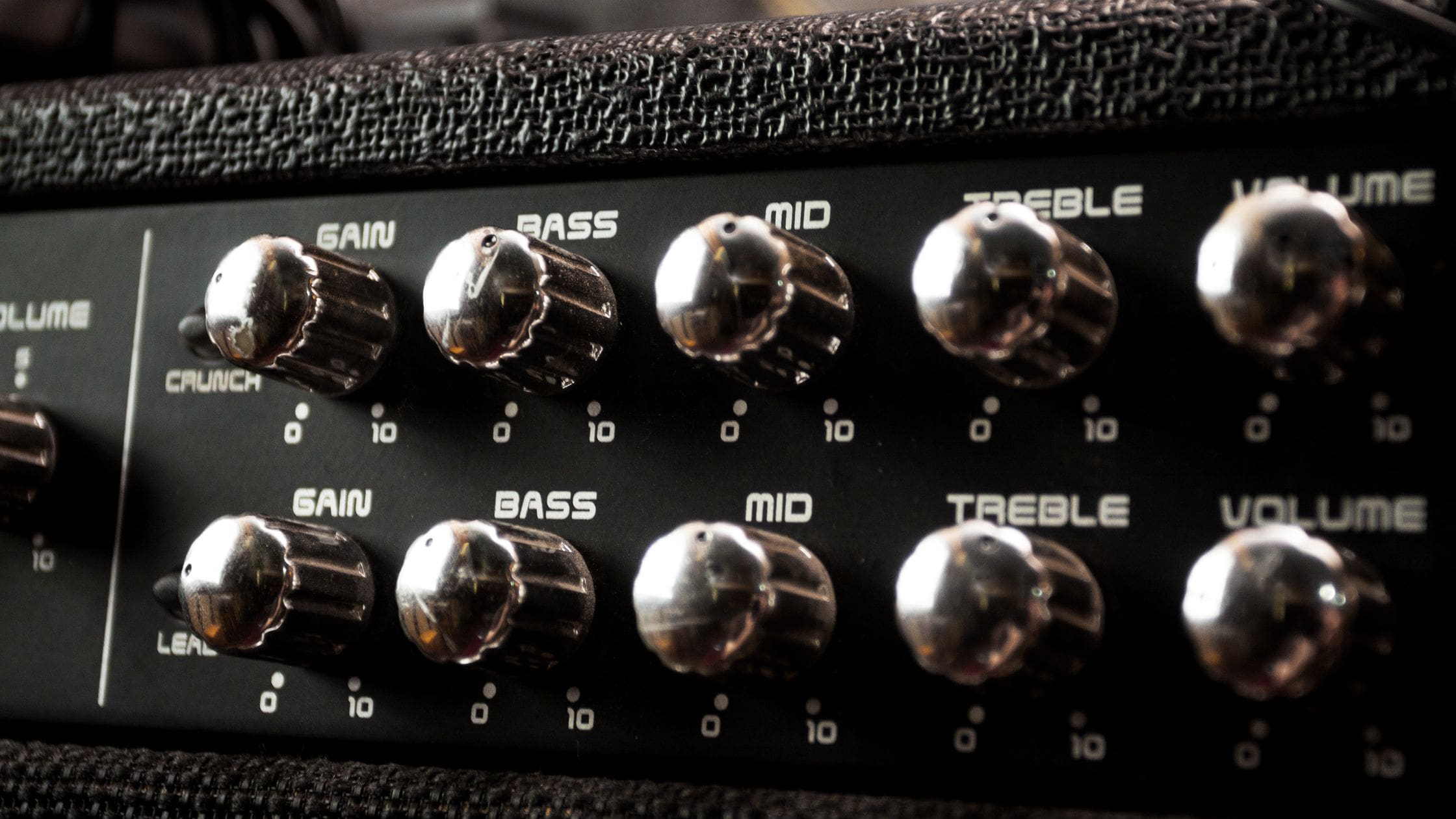
An electronic amplifier is a circuit or a standalone device that is designed to increase the magnitude of an input signal going into it. They are the opposite of attenuators, that are designed to reduce the magnitude of a signal.
In the world of amplifiers, the change in amplitude is referred to as the “gain” (symbolized by the letter “A”). The gain is generally measured in decibels (dB), and is expressed as the ratio of output over input.
Amplification can be applied to voltage, current, or power signals, and mathematically, the gain for each of those types is expressed as follows:
Voltage Gain:
𝐴𝑣 = 𝑉out 𝑉in
Current Gain:
𝐴i = Iout Iin
Power Gain:
𝐴p = Pout Pin
While gain ratios are essentially linear, they are expressed in decibels which follow a linear function. This helps to keep the numbers manageable, especially when dealing with large gains which can be several orders of magnitude larger than the input signal.
To calculate the gain in dB, the following formulas are used:
Voltage or current gain (dB) = 20 log10 𝐴v
Power gain (dB) = 10 log10 𝐴p
Note that while voltage or current amplifies only boost voltage or current, power amplifiers boost both signal and current to increase the power gain.
If the gain of an amplifier is more than 1, then the signal is amplified (the signal is stronger at the output than at the input). If the gain is equal to one, then there is no change. If the resulting gain is less than 1, then the signal is attenuated.
Amplifiers can come in both linear and non-linear varieties. The linearity is a reference to the proportionality of the output with regard to the input. Many linear amplifiers are intended to preserve the shape of the original input signal as much as possible.
Non-linear amplifiers, on the other hand, tend to introduce some distortion or overdrive into the signal, often resulting in a differently shaped signal waveform.
How Does an Electronic Amplifier Work?
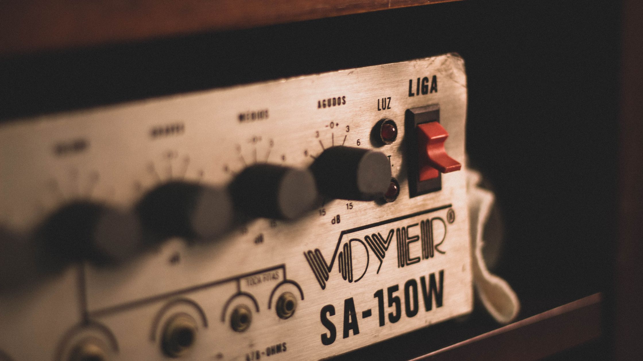
An electronic amplifier increases the amplitude of an input signal by modulating power from an external supply. It achieves this through active components (either with transistors or vacuum tubes) that control current flow based on the input signal, producing a proportional but more powerful output.
Amplifiers consist of two key circuits: the input stage, which receives and processes the signal, and the output stage, which draws energy from the power supply to drive a load.
What are the Core Electronic Amplifier Properties?
Amplifiers are characterized by several key properties that define their performance.
- Gain is the ratio of output to input (voltage, current, or power), often expressed in decibels (dB). Bandwidth determines the range of frequencies an amplifier can process without significant attenuation.
- Linearity measures how faithfully the output follows the input; poor linearity introduces distortion, such as harmonic or intermodulation distortion. Negative feedback is often used to improve linearity and reduce distortion from 5% to as low as 0.001%.
- Efficiency is crucial in power amplifiers, representing how much input power is converted into useful output rather than wasted as heat.
- Impedance matching (input and output impedance) affects signal transfer and loading.
- Slew rate limits how fast the output can change, impacting high-speed signals.
- Stability prevents unwanted oscillations, and dynamic range defines the smallest and largest signals an amplifier can handle while preserving signal integrity.
What are the Different Electronic Amplifier Types and Categories?

Electronic amplifiers come in many forms, each tailored for specific functions and performance requirements. They can be categorized based on several key metrics, as follows:
- Classed by input/output parameters: Amplifiers are classified as voltage, current, transresistance, or transconductance amplifiers, depending on how they manipulate electrical signals.
- Classed by conduction angle, linearity, and efficiency: Power amplifiers are divided into classes A, B, AB, and D. These classifications determine the portion of the input cycle during which the output device conducts and how efficiently the amplifier converts input DC power to output AC power.
- Classed by frequency range: This category divides them into audio, RF, ultrasonic, or wideband amplifiers, each optimized for different signal types.
- Classed by function: This class breaks them down into preamplifiers, power amplifiers, buffers, or operational amplifiers.
- Finally, classifying by technological implementation differentiates between vacuum tube, transistor-based, and IC amplifiers.
Electronic Amplifier Classification Based on Output
As mentioned previously, electronic amplifiers can be categorized into three types based on their output, having either voltage, current, transresistance, or transconductance outputs.
Voltage Amplifier
A voltage amplifier increases the output voltage amplitude relative to the input signal. These amplifiers are commonly used in audio systems, instrumentation, and small-signal circuits. They are designed for high voltage gain with low current gain, making them ideal for preamplifiers or front-end stages in applications like radio receivers.
Typically, voltage amplifiers have high input impedance and low output impedance, which minimizes the loading effect on preceding stages and ensures efficient signal transfer without compromising the integrity of earlier components.
While excellent for signal conditioning, voltage amplifiers are not suited for driving high-power loads, as their focus is on amplifying voltage rather than supplying large amounts of current.
Current Amplifier
A current amplifier increases the output current amplitude relative to the input signal. Less common than voltage amplifiers, current amplifiers are primarily used for impedance transformation or for driving loads that require higher current, such as motors or actuators. They are especially useful in sensor interfaces, where a small current must be amplified to a level suitable for actuation or processing.
Current amplifiers are characterized by low input impedance and high output impedance, allowing them to draw minimal current from the source while delivering higher current to the load.
While excellent for current-driven applications, they may not be suitable for high-voltage applications, as their design focuses on current rather than voltage gain.
Transresistance Amplifier
A transresistance amplifier converts input current into output voltage. Often referred to as a current-to-voltage converter, these amplifiers are essential in applications where current needs to be translated into a voltage signal, such as in photodiode circuits or sensor interfaces.
Transresistance amplifiers are particularly useful in instrumentation and sensor systems, where the signal is often a current proportional to a physical parameter (like light intensity or temperature).
They are characterized by a low input impedance and a high output impedance, allowing them to effectively convert small currents to measurable voltages without significant signal distortion.
While effective for current-to-voltage conversion, transresistance amplifiers may not be suitable for high-power applications where current or voltage needs to be increased significantly.
Transconductance Amplifier
A transconductance amplifier converts input voltage into output current. These amplifiers are used where it’s necessary to drive a load with a current that is proportional to an input voltage signal, such as in audio or RF circuits.
Common in control systems, transconductance amplifiers can be employed to drive the control elements in motor controllers or audio amplifiers. They provide excellent linearity and are ideal for applications requiring precise control of current output.
Transconductance amplifiers have high input impedance and low output impedance, making them ideal for interfacing with voltage sources and driving low-impedance loads.
While suitable for voltage-to-current conversion, transconductance amplifiers may not be the best choice for high-power applications due to their limitations in power delivery compared to power amplifiers.
Electronic Amplifier Classification Based on Conduction Angle/Linearity
A power amplifier increases the power of a signal, which is the product of its voltage and current.
These amplifiers are designed to drive specific loads, such as speakers or transmitters, making them essential in audio and RF systems.
They can be grouped into different classes based on their conduction angle (the portion of the input cycle during which the output device conducts) and efficiency (the ratio of output AC power to input DC power).
Class A Operation
Class A amplifiers operate with full-cycle conduction, where the output device conducts throughout the entire input signal cycle. However, the efficiency of Class A amplifiers is generally poor, typically below 30%, as the output device remains active throughout the input signal cycle, even when no amplification is required.
Key features include:
- Conduction angle: The output device conducts for nearly the entire input signal cycle (close to 360°), contributing to its high linearity but low efficiency.
- High linearity: The amplifier maintains excellent fidelity, with minimal distortion, making it ideal for high-quality audio applications.
- Low distortion: Because the amplifier conducts for the entire cycle, distortion is kept at a minimum, ensuring a clean output signal.
- Bias point: Set near the midpoint of the load line, ensuring maximum undistorted swing.
- Variants: Transformer-coupled and push-pull Class A designs aim to improve power handling and reduce power dissipation, though they still struggle with efficiency limitations.
Class A amplifiers are often favored in high-end audio and other applications where signal quality is paramount, despite their inefficiency.
Class B Operation
Class B amplifiers operate with half-cycle conduction, where each transistor conducts for one-half of the input signal cycle. Push-pull configuration: Pairs of transistors are used in a push-pull arrangement to recreate the full waveform and minimize distortion.
- Conduction angle: The output device conducts for 180° of the input signal cycle, meaning each transistor only amplifies one-half of the waveform.
- Higher efficiency: Class B amplifiers are much more efficient than Class A, as there is little to no current flow during the zero input phase, reducing wasted power.
- Crossover distortion: A common issue at the zero crossing where conduction transitions from one transistor to the other, leading to distortion.
- Bias point: Typically, the bias point is set near the cutoff, ensuring that neither transistor conducts during the entire cycle, improving efficiency but contributing to crossover distortion.
- Variants: Some designs, like complementary push-pull Class B, use both NPN and PNP transistors to further reduce distortion.
Class B amplifiers are a more power-efficient alternative to Class A amplifiers, but crossover distortion limits their ideal application.
Class AB Operation
Class AB amplifiers represent a compromise between Class A and Class B, combining the best features of both for improved performance. Popular in audio applications: Due to their good balance of efficiency, fidelity, and manageable heat dissipation, Class AB amplifiers are widely used in audio amplification, especially in high-fidelity audio systems.
- Conduction angle: The output devices conduct between 180° and 360° of the input signal cycle, meaning each transistor is slightly biased to conduct over a portion of the signal and avoid the severe crossover distortion of Class B.
- Moderate efficiency: Class AB amplifiers offer better efficiency than Class A, typically ranging from 50% to 70%, while still maintaining relatively low distortion.
- Reduced distortion: The biasing reduces crossover distortion, resulting in a smoother transition between devices and better overall fidelity compared to Class B.
- Bias point: The devices are biased slightly above cut-off, ensuring both high efficiency and reduced distortion.
- Variants: Variants include designs that optimize for lower distortion or better efficiency, depending on the specific application needs.
Class AB amplifiers are a popular choice in applications where a balance between power efficiency and sound quality is important.
Class C Operation
Class C amplifiers are designed for high-efficiency operation, primarily used in applications requiring high-frequency signals. Applications: Commonly used in radio frequency (RF) transmitters and resonant circuits, where the signal can be filtered to recover a usable waveform.
- Conduction angle: The output device conducts for less than 180° of the input signal cycle, which makes Class C amplifiers highly efficient, with efficiencies often exceeding 80-90%.
- High efficiency: Due to the limited conduction, Class C amplifiers are more efficient than Class A and Class B designs, making them ideal for power-sensitive applications.
- Severe distortion: The signal is heavily distorted during the off period, which makes Class C amplifiers unsuitable for audio applications.
- Bias point: Devices are biased to conduct only during a specific portion of the input cycle, which maximizes efficiency but contributes to distortion.
- Variants: Variants include tunable designs optimized for specific RF frequencies or bandwidths.
Class C amplifiers are most suitable for high-frequency applications, particularly where signal fidelity is less critical and efficiency is paramount.
Class D Operation
Class D amplifiers operate using switching techniques to achieve high efficiency, making them ideal for modern power-sensitive applications. Applications: Commonly used in consumer electronics, audio amplifiers, portable devices, and any application where power efficiency and compact design are essential.
- Conduction angle: The output transistors operate in an on/off state, meaning they do not conduct during the entire input cycle, resulting in significantly reduced power loss.
- High efficiency: Class D amplifiers achieve efficiencies above 90%, greatly reducing heat dissipation and making them more power-efficient compared to linear amplifiers.
- Severe distortion: While highly efficient, switching amplifiers can introduce high-frequency noise and distortion, which is mitigated using output filters.
- Bias point: No traditional bias point is used as the transistors operate in a switching mode, turning fully on or off, rather than operating in a linear region.
- Variants: Includes PWM (Pulse-Width Modulation) and other switching techniques, both requiring additional filtering to smooth the output signal.
Class D amplifiers are popular in modern audio amplification and electronic devices, where size, efficiency, and low heat dissipation are priorities.
Electronic Amplifier Classification Based on Frequency Range
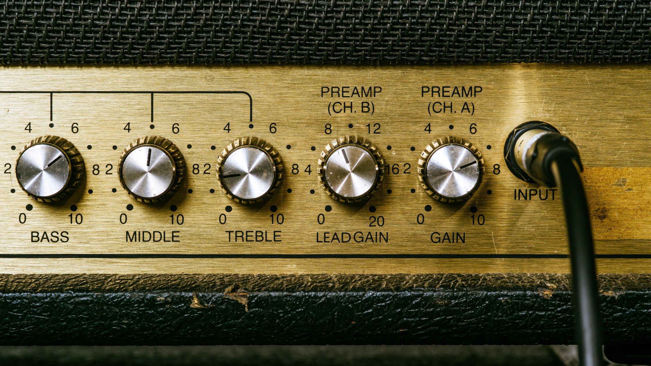
Electronic amplifiers can also be categorized according to their operating frequencies. Such devices include audio, radio frequency, ultrasonic, microwave, and wideband designs. Each type is optimized for its respective signal types.
Audio Frequency Amplifiers
Audio frequency amplifiers, such as those found in home entertainment systems, musical instruments, and public address systems, use an audio signal as an input and then boost the amplitude to increase the volume.
- Operate in the 20 Hz – 20 kHz range, sometimes extending beyond 100 kHz in high-fidelity systems.
- Designed for low distortion and adequate power output to drive loudspeakers or headphones.
Radio Frequency (RF) Amplifiers
Radio-frequency amplifiers are found extensively in wireless communication, radar, and broadcasting, where they amplify signals for reliable transmission and reception.
Some designs, such as low-noise amplifiers (LNAs), enhance weak signals in receivers, while power amplifiers (PAs) boost transmission signals in communication systems.
- Operate in the kHz to GHz range, depending on application needs.
- Designed for impedance matching, noise minimization, and linearity to prevent signal loss and distortion.
Ultrasonic Amplifiers
Ultrasonic amplifiers are used in medical imaging, industrial cleaning, and non-destructive testing, where they amplify signals beyond the range of human hearing. These amplifiers must handle high-frequency waveforms with precision to ensure
Specialized transducers convert the amplified electrical signals into ultrasonic waves for practical use.
- Operate above 20 kHz, often reaching several MHz in medical and industrial applications.
- Designed for high-frequency signal stability and efficient power transfer to ultrasonic transducers.
Microwave Amplifiers
Microwave amplifiers are essential in radar, satellite communications, and high-frequency data transmission. These amplifiers operate at much higher frequencies than standard RF amplifiers, often requiring specialized components and materials to ensure efficiency and reliability.
- Operate in the GHz range, supporting high-frequency communication and radar systems.
- Designed for minimal signal loss and phase distortion using waveguides and advanced semiconductor materials.
Wideband Amplifiers
Wideband amplifiers are designed to amplify signals over a broad frequency range, making them essential in test equipment, broadband communication systems, and signal processing. This makes them ideal for applications like oscilloscopes, spectrum analyzers, and ultra-wideband communications.
- Operate across a broad frequency range, from near-zero Hz to MHz or even GHz in advanced designs.
- Designed for minimal signal distortion and flat gain response across wide bandwidths.
Electronic Amplifier Classification Based on Functionality
Amplifiers can be classified based on their primary function or the role they play in manipulating signals. These classifications include:
- Preamplifiers: Amplify weak input signals to a level suitable for further processing without significantly altering signal characteristics.
- Power Amplifiers: Deliver high power to drive a load, such as a speaker or antenna.
- Driver Amplifiers: Provide higher current or voltage to drive the final stage of an amplifier system.
- Buffer Amplifiers: Maintain voltage amplitude while offering the ability to drive high current without signal distortion.
- Operational Amplifiers (Op-Amps): Versatile components used in a range of applications, from filters to comparators.
- Weak-Signal or Low-Noise Amplifiers (LNAs): Designed for high gain with minimal noise addition, essential for RF receivers or instrumentation.
Electronic Amplifier Classification Based on Technology
Amplifiers can also be categorized based on the technology used in their construction. The key types are vacuum tube, transistor-based, and integrated circuit (IC) amplifiers, each offering distinct advantages and disadvantages based on their design, efficiency, and application.
Vacuum Tube Amplifiers
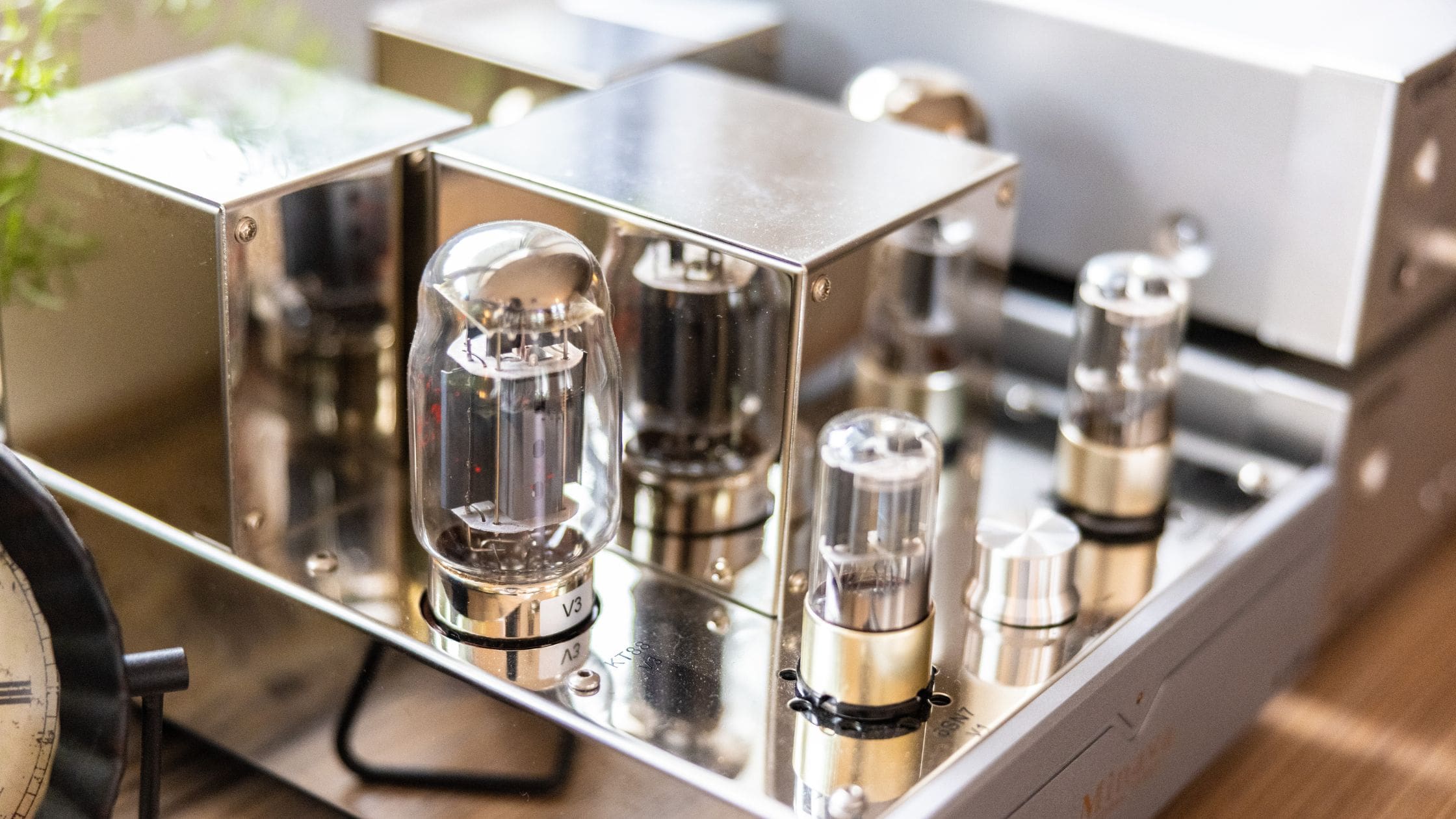
Vacuum tube amplifiers, also known as tube amps, use thermionic emission from heated cathodes to control electron flow in a vacuum. They are often prized for their warm sound characteristics, making them popular in high-end audio systems and certain guitar amplifiers.
- Advantages: High power output, preferred by audiophiles for tonal warmth.
- Disadvantages: Bulky, inefficient, and prone to degradation over time.
Transistor-Based Amplifiers
Transistor amplifiers use semiconductor components, such as bipolar junction transistors (BJTs) or field-effect transistors (FETs), to amplify electrical signals. They are more compact, durable, and efficient than vacuum tube amplifiers, leading to widespread use in consumer electronics and audio equipment.
- Advantages: Smaller, more energy-efficient, longer-lasting.
- Disadvantages: May lack the unique tonal characteristics of tube amplifiers.
Integrated Circuit (IC) Amplifiers
IC amplifiers are built using integrated circuits that contain multiple transistors on a single chip, offering compactness and reliability. These are commonly used in consumer electronics, automotive systems, and portable devices due to their small size and cost-effectiveness.
- Advantages: Highly integrated, low cost, power-efficient.
- Disadvantages: May have limitations in power handling or audio fidelity compared to tube or transistor-based designs.
What are the Advantages of Electronic Amplifiers?
Electronic amplifiers provide the advantage of amplifying small signals to drive larger loads, such as loudspeakers or antennas, enabling the operation of high-power devices.
They improve long-distance communication in telephony, broadcasting, and data links by ensuring signal integrity. Integrated amplifiers are compact, cost-effective, and reliable, offering space and cost savings. Additionally, modular designs enable easy scalability, making them adaptable for varying power or frequency requirements in diverse applications.
What are the Disadvantages of Electronic Amplifiers?
Electronic amplifiers, particularly high-power ones, can generate substantial heat, requiring effective heat sinks or cooling systems to prevent damage. Non-idealities in components can introduce noise and distortion, necessitating careful design to minimize these issues.
Biasing can drift over time and with temperature changes, potentially introducing offsets or distortion in the output. Very high-power stages face risks of device failure if cooling or bias control is inadequate, emphasizing the need for precise thermal management and stability in design.
How Are Amplifiers Used in Motion Control?
And finally, we get to the crux of this article. Being a company focused on motion control, it is only proper that we give a nod to a key component in industrial automation – the servo driver!
Servo Drivers and Servo Amplifiers
A servo drive is a specialized power amplifier used in motion control systems to regulate the voltage and current supplied to servo motors. They are essential in ensuring that the motor operates efficiently, with precise control over parameters like position, velocity, and torque.
Unlike typical power amplifiers, servo amplifiers are designed for high performance in dynamic systems, where rapid adjustments are necessary. They are typically built on Class D or switching-mode topologies, which provide high energy efficiency by minimizing power loss and reducing heat generation.
Key Features:
- Closed-loop Control: Servo amplifiers continuously adjust the motor’s output in real-time by analyzing feedback from encoders or resolvers, ensuring precise motion and minimizing error.
- Low Distortion: These amplifiers are designed to minimize signal distortion, ensuring smooth and accurate motor operation.
- High Efficiency: Built on energy-efficient topologies, servo amplifiers reduce power loss and heat generation, improving the system’s overall energy performance.
- Rapid Adjustment: The servo amplifier can quickly respond to changes in the control signal, ensuring the motor operates effectively even in dynamically changing environments.
Key Parameters of Servo Drives
Servo drives offer extensive control over various motor performance parameters, and they are highly customizable to the user’s needs. They can be programmed either via a GUI on the servo drive hardware itself, or via a computer interface. The most critical adjustable parameters include:
- Speed: Controls the motor’s rotational velocity (measured in RPM or rad/s), with parameters like Maximum Operating Speed and Speed Response Time tuned to suit the application, ensuring smooth and responsive movement.
- Torque: Sets the motor’s rotational force (measured in Nm or oz-in), with parameters such as Maximum Torque and Continuous Torque optimized for load handling and system efficiency.
- Position: Enables precise control over motor placement, with parameters like Target Position and Position Accuracy ensuring that the motor reaches the desired position accurately.
- Acceleration/Deceleration: Defines how quickly the motor accelerates and decelerates. Parameters like Maximum Acceleration Rate and Acceleration Profile Shape control smooth and controlled motion transitions.
- Control Gains: PID control settings, such as Proportional Gain (Kp), Integral Gain (Ki), and Derivative Gain (Kd), help fine-tune the system’s responsiveness and stability, ensuring smooth and reliable operation.
- Feedback: Continuous data from sensors (like encoders or resolvers) provide real-time feedback that allows the servo drive to adjust motor performance for optimal precision.
- Limit Settings: Safety parameters like Maximum Torque Limit and Maximum Speed Limit protect the system from exceeding safe operational limits, preventing damage to components.
Conclusion
As we have shown in this article, amplifiers are the unsung heroes of modern electronics. Whether they’re keeping factory robots in sync, making sure your Wi-Fi signal doesn’t drop mid-scroll, or delivering that blistering guitar solo at a live concert, these electronic workhorses are everywhere.
Thanks to advancements in semiconductor wizardry, digital control, and some serious engineering know-how, amplifiers have become smaller, smarter, and far more efficient. Gone are the days of bulky, power-hungry designs, as today’s amplifiers are lean, mean, signal-boosting machines.
From the precision of motion control to the depths of high-fidelity audio, amplifiers will continue to evolve, ensuring that everything from your morning playlist to the next big aerospace breakthrough comes through loud and clear.


